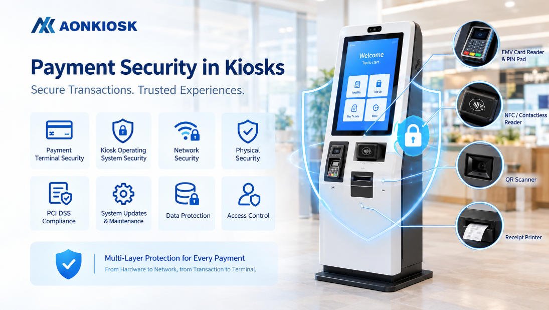






A self-service kiosk is not simply a touchscreen installed inside a metal cabinet. It is a complete hardware platform in which the enclosure, display, computing system, power system, communication interfaces, peripheral devices, cooling components, and service structure must operate together.
Understanding the kiosk hardware structure is important for system integrators, software developers, equipment distributors, project engineers, and end users. A well-designed structure makes the kiosk easier to install, integrate, maintain, troubleshoot, and upgrade throughout its service life.
This knowledge-base guide explains how the physical and electronic layers of a kiosk are organized, how the major modules connect, and what should be checked when planning or servicing a commercial self-service terminal.
For a detailed list of individual devices, refer to our guide to the main components of a self-service kiosk.
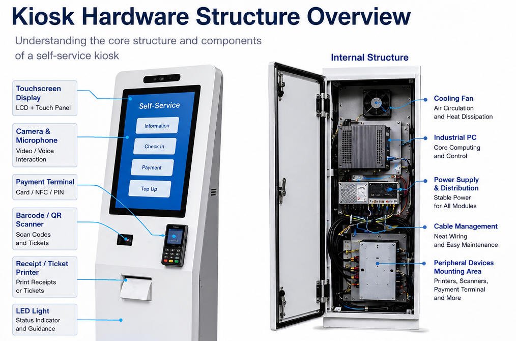
1. What Is a Kiosk Hardware Structure?
A kiosk hardware structure is the physical and electronic architecture that supports all kiosk functions.
It normally includes six interconnected layers:
- Mechanical enclosure
- Display and user-interaction layer
- Computing and control layer
- Peripheral and transaction layer
- Power, networking, and thermal-management layer
- Security and maintenance layer
These layers should not be designed independently. The dimensions of the enclosure affect the display position, internal airflow, printer paper path, cable routing, service access, and installation method.
Similarly, the selected peripherals determine the number of USB, serial, LAN, audio, and power connections required from the computer and internal power-distribution system.
A reliable kiosk therefore depends on coordinated mechanical, electrical, and integration engineering.
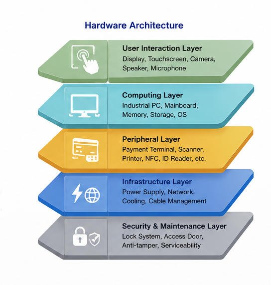
2. Simplified Kiosk Hardware Architecture
A typical self-service kiosk can be represented by the following structure:
Kiosk Enclosure
│
├── User Interaction Layer
│   ├── LCD Display
│   ├── Touch Panel
│   ├── Camera
│   ├── Speaker
│   └── Microphone
│
├── Computing Layer
│   ├── Industrial PC or Android Mainboard
│   ├── Memory and Storage
│   ├── Operating System
│   └── I/O Interfaces
│
├── Transaction and Peripheral Layer
│   ├── Payment Terminal
│   ├── NFC Reader
│   ├── Barcode or QR Scanner
│   ├── Receipt Printer
│   ├── ID or Passport Reader
│   └── Optional Application Modules
│
├── Infrastructure Layer
│   ├── AC Input
│   ├── Power Supply
│   ├── Power Distribution
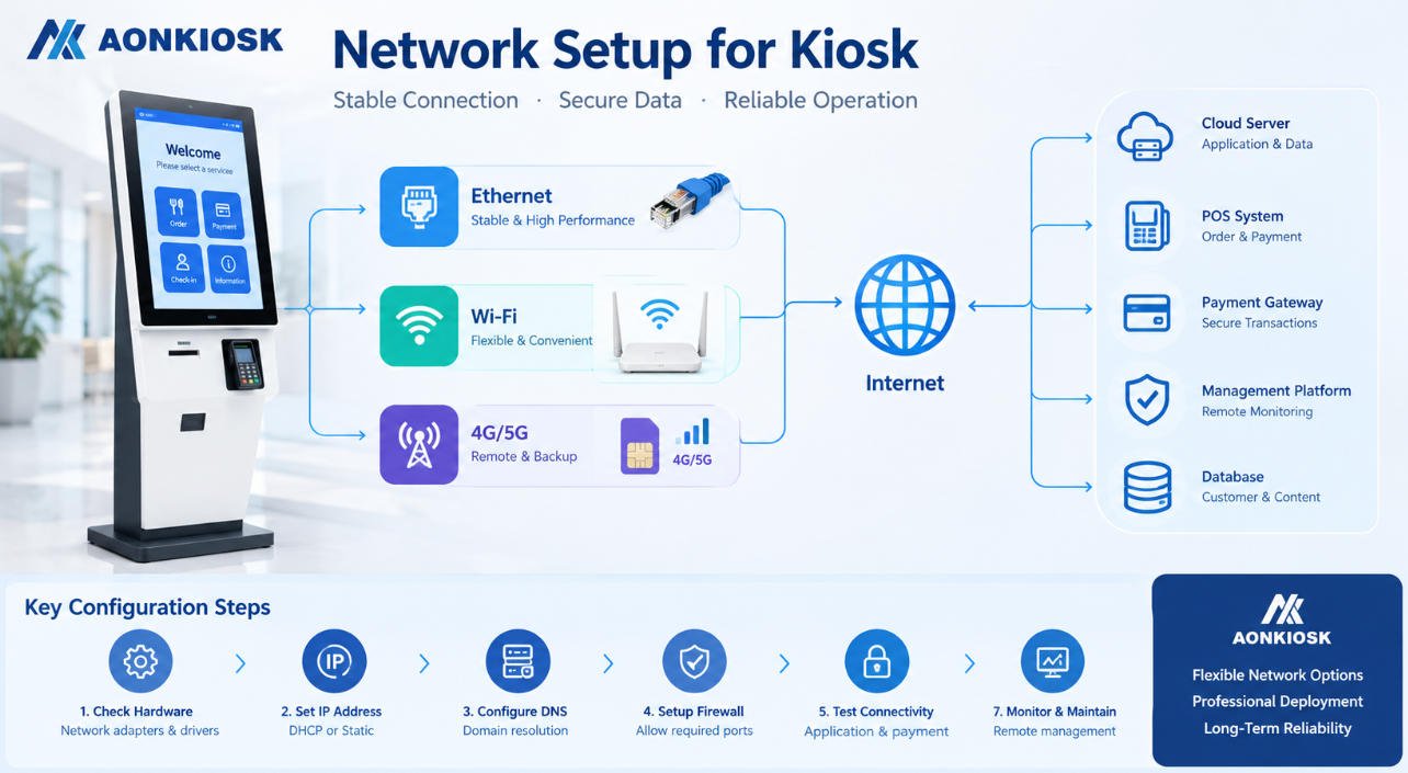
│   ├── LAN, Wi-Fi, or 4G/5G
│   ├── Cooling Fans
│   └── Cable Management
│
└── Mechanical and Service Layer
    ├── Door and Lock System
    ├── Internal Mounting Brackets
    ├── Maintenance Access
    ├── Floor or Wall Fixing Points
    └── Security and Anti-Tamper Features
The exact configuration varies according to the kiosk application. A restaurant ordering kiosk may require a payment terminal, QR scanner, and receipt printer, while a hotel check-in kiosk may also require a passport reader, camera, key-card dispenser, and signature device.
3. Mechanical Enclosure Structure
The enclosure is the structural foundation of the kiosk. It supports the screen and internal devices while protecting electrical components from users, accidental impact, dust, unauthorized access, and environmental exposure.
3.1 Common Enclosure Materials
Commercial kiosk enclosures are commonly manufactured from:
- Cold-rolled steel
- Stainless steel
- Aluminum alloy
- Tempered glass
- Engineering plastics for selected covers or trim parts
Cold-rolled steel is frequently used for indoor floor-standing kiosks because it provides a practical balance between strength, manufacturability, surface quality, and cost.
Stainless steel may be selected for humid, corrosive, food-service, medical, or semi-outdoor environments. Aluminum can reduce weight but may require additional reinforcement depending on the kiosk dimensions and mounting arrangement.
3.2 Internal Frame and Outer Panels
A kiosk enclosure normally consists of two structural groups.
The internal frame carries the main mechanical load. It holds the display, computer, printer, power supply, scanner, payment device, fans, and cable-management components.
The outer panels provide the visible product appearance and prevent direct access to internal components.
Separating the supporting frame from decorative panels can simplify assembly and allow branding panels to be modified without redesigning the complete internal structure.
3.3 Installation Structures
Common installation formats include:
- Floor-standing kiosk
- Countertop kiosk
- Desktop terminal
- Wall-mounted kiosk
- Embedded or in-wall kiosk
- Mobile kiosk with lockable casters
- Outdoor or semi-outdoor kiosk
A floor-standing kiosk should normally include a wide, stable base and appropriate fixing holes. In public environments, anchoring the base to the floor may be necessary to reduce tipping or unauthorized movement.
Wall-mounted models require verification of the wall structure, bracket load rating, cable-entry position, and maintenance clearance.
3.4 Mechanical Design Checks
Before production, engineers should verify:
- Center of gravity
- Base stability
- Screen support strength
- Door deformation
- Hinge loading
- Printer paper-loading clearance
- Peripheral removal path
- Cable bend radius
- Ventilation openings
- Transportation and packaging loads
A kiosk may look stable in a CAD drawing but become unbalanced after a heavy printer, cash module, or large payment terminal is installed. Structural evaluation must therefore use the final hardware configuration.
4. Display and Touchscreen Assembly
The display assembly is the primary interface between the kiosk and the user. It normally includes an LCD panel, touch sensor, protective glass, display controller, mounting frame, and related signal and power cables.
4.1 Commercial Display
Kiosk displays are generally selected according to:
- Screen size
- Resolution
- Brightness
- Viewing angle
- Orientation
- Operating temperature
- Backlight lifetime
- Continuous-operation requirements
Common kiosk display sizes range from compact 15.6-inch panels to 21.5-inch, 27-inch, 32-inch, and larger commercial displays.
Indoor kiosks may operate effectively with standard brightness, while kiosks installed near windows or in high-ambient-light environments may require a high-brightness panel.
4.2 Touch Technology
Projected capacitive touch, commonly called PCAP touch, is widely used in modern kiosks because it supports responsive multi-touch interaction and a flat glass surface.
Infrared touch may be selected for larger displays or applications requiring alternative touch behavior.
The touch controller usually communicates with the kiosk computer through USB. The LCD image signal may use HDMI, DisplayPort, eDP, LVDS, or another interface depending on the system design.
4.3 Protective Glass and Mounting
The front glass provides a cleanable interaction surface and helps protect the display.
Engineering considerations include:
- Glass thickness
- Edge treatment
- Surface hardness
- Anti-glare treatment
- Optical bonding requirements
- Touch sensitivity through the glass
- Gasket or adhesive selection
- Replacement accessibility
The display bracket should hold the panel securely without applying excessive pressure to the LCD frame. Uneven mounting force can cause panel distortion, light leakage, or long-term reliability problems.
Common Display Symptoms
| Symptom | Possible Hardware Cause |
|---|---|
| Screen has no image | Loose display cable, incorrect input source, display power failure |
| Touch does not respond | Disconnected USB cable, touch driver issue, controller failure |
| Touch position is inaccurate | Calibration issue, incompatible resolution, glass interference |
| Screen flickers | Unstable power, loose signal cable, damaged display controller |
| Display is too dark | Incorrect brightness setting, backlight degradation, unsuitable panel specification |
Always disconnect the kiosk from mains power before opening the enclosure or reseating internal display cables.
5. Computing and Control Structure
The computing system processes user input, runs the kiosk application, communicates with backend systems, and controls connected peripherals.
Depending on project requirements, the kiosk may use:
- Industrial mini PC
- Fanless embedded computer
- x86 motherboard
- ARM-based Android mainboard
- Panel PC
- Custom embedded control board
5.1 Main Computing Components
The computing layer normally contains:
- Processor
- RAM
- SSD, eMMC, or other storage
- Graphics output
- USB ports
- Ethernet interface
- Serial ports
- Audio interface
- Wi-Fi or cellular module
- Operating-system image
Windows is frequently used where broad peripheral-driver support is required. Android may be suitable for streamlined touch applications, while Linux can be used for customized embedded deployments.
The hardware platform should be selected according to the software workload rather than screen size alone.
Applications involving video playback, computer vision, multiple displays, real-time analytics, or advanced user interfaces may require more processing power than basic ticketing or information-query applications.
5.2 Industrial PC Placement
The computer should be positioned where it:
- Receives adequate airflow
- Remains accessible for maintenance
- Does not block paper replacement
- Is protected from liquid entry
- Allows convenient cable connection
- Can be replaced without removing unrelated modules
Mounting the computer behind several fixed devices may reduce cabinet size, but it can significantly increase service time.
5.3 I/O Capacity Planning
A common integration mistake is underestimating the number and type of ports required.
Before finalizing the computer, prepare an interface list:
| Device | Typical Interface |
| Touch controller | USB |
| Barcode scanner | USB or RS232 |
| Receipt printer | USB, RS232, or Ethernet |
| NFC reader | USB or serial |
| Payment terminal | USB, serial, or Ethernet |
| Camera | USB |
| Display | HDMI, DisplayPort, LVDS, or eDP |
| Network connection | Ethernet, Wi-Fi, or cellular |
| Service sensor | GPIO, USB, or serial |
USB hubs may be used, but powered industrial hubs are preferable when several devices require stable current or continuous communication.
6. Peripheral Integration Structure
Peripheral devices allow the kiosk to perform application-specific tasks. They should be arranged according to the user workflow, internal clearance, device communication requirements, and maintenance frequency.
6.1 Barcode and QR Scanner
A barcode or QR scanner may be used to read:
- Product barcodes
- Mobile payment codes
- Membership codes
- Electronic tickets
- Order numbers
- Identity documents
The scanner window should provide a suitable reading angle and should not be obstructed by the cabinet edge.
Ambient light, reflective glass, scanner depth, focal distance, and the expected code size should be evaluated during prototype testing.
6.2 Receipt and Ticket Printer
Thermal printers require careful structural planning because they include moving paper, a paper roll, a cutter, sensors, and a paper-exit path.
The enclosure should provide:
- Sufficient paper-roll clearance
- Easy paper replacement
- A direct paper-output path
- Access to the cutter and print head
- Space for cable movement
- Protection against users pulling internal components
A poorly aligned paper exit can cause frequent paper jams even when the printer itself is functioning correctly.
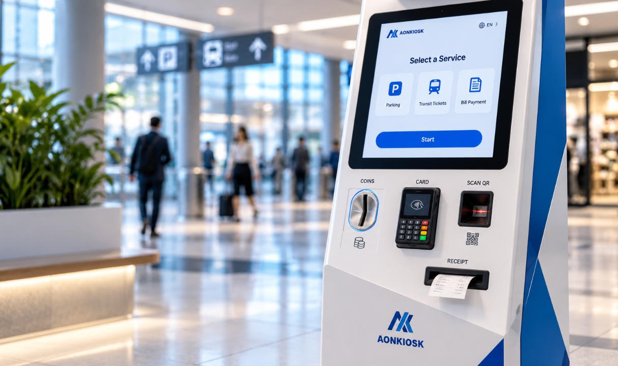
6.3 Payment Terminal
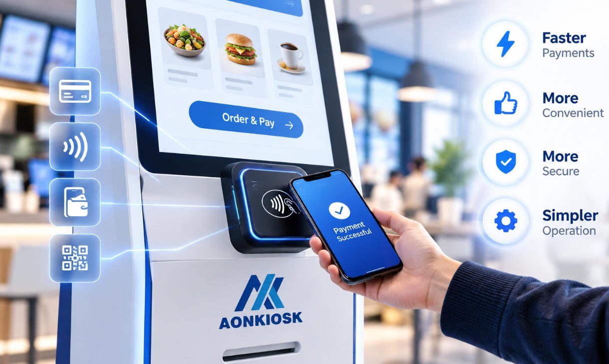
Payment-terminal integration may involve:
- Card insertion
- Contactless NFC tapping
- Magnetic-stripe reading
- PIN entry
- QR-code payment
- Mobile-wallet payment
The payment terminal should be mounted at a comfortable height and angle. Its card slot, NFC zone, keypad, display, and accessibility features must remain unobstructed.
Payment devices are often supplied or certified by third-party payment providers. The kiosk structure should therefore be designed around the selected terminal model rather than around an approximate device size.
For transaction-oriented configurations, see AONKIOSK’s retail and payment kiosks.
6.4 Optional Application Modules
Depending on the industry, a kiosk may also integrate:
- RFID reader
- Passport scanner
- ID-card reader
- Fingerprint reader
- Facial-recognition camera
- Document scanner
- Card dispenser
- Key-card encoder
- Cash acceptor
- Coin dispenser
- Cash recycler
- Label printer
- Signature pad
- Weighing module
- LED status indicator
Each additional device affects enclosure size, weight, power consumption, heat generation, communication-port requirements, software drivers, and service procedures.
7. Power Supply and Electrical Distribution
The power structure converts the building’s AC input into the voltage levels required by the computer, display, printer, scanner, network equipment, fans, and other modules.
A typical internal arrangement may include:
- AC power inlet
- Main power switch
- Fuse or circuit protection
- EMI filter
- Surge-protection device
- AC distribution terminals
- AC-to-DC power supplies
- DC distribution board
- Grounding connections
- Optional uninterruptible power supply
7.1 Power Budget
The total rated power of all internal devices should be calculated before selecting the power supply.
The calculation should include:
- Computer peak consumption
- Display and backlight consumption
- Printer peak load during printing and cutting
- Payment terminal consumption
- Scanner and camera consumption
- Cooling fans
- Network modules
- Spare capacity for future expansion
Printers and electromechanical modules can create short peak loads. Selecting a power supply based only on average consumption may lead to random restarts or device disconnections.
7.2 Grounding
Metal kiosk enclosures should use proper protective grounding.
Grounding connections should be secure, clearly identified, and designed so that removable doors or panels remain safely bonded where required.
Power wiring should be separated from low-voltage signal cables where practical to reduce electrical interference.
7.3 Electrical Troubleshooting
If the complete kiosk does not power on, check the following in order:
- Confirm that the external outlet has power.
- Check the power cable and inlet connection.
- Verify the main switch position.
- Inspect the fuse or circuit-protection device.
- Check whether the internal power supply has an input indicator.
- Measure the DC output only with suitable equipment and qualified personnel.
- Disconnect optional peripherals to identify a possible overloaded or shorted branch.
Do not bypass a fuse, grounding connection, or protective component during troubleshooting.
8. Thermal Management and Ventilation
Heat is generated by the processor, display backlight, power supplies, printers, cellular modules, and other electronics.
Without a suitable thermal-management structure, internal temperatures may rise above the operating range of the components.
Common thermal-control methods include:
- Natural convection
- Forced-air cooling
- Filtered intake vents
- Exhaust fans
- Heat sinks
- Fanless industrial computers
- Temperature-controlled fans
- Air conditioning for specialized outdoor kiosks
8.1 Airflow Design
Air should enter through a lower or cooler area and exit through an upper or warmer area.
Cables, paper rolls, mounting plates, and power supplies should not block the airflow path.
Fans should be positioned so that they remove heat from the cabinet rather than circulating hot air within a closed compartment.
8.2 Maintenance Considerations
Ventilation filters can accumulate dust and should be accessible for periodic cleaning.
Common overheating symptoms include:
- Unexpected computer shutdown
- Application freezing
- Display instability
- Printer communication errors
- Fan noise
- Reduced component life
If the kiosk operates normally with the door open but fails after the door is closed, restricted airflow or excessive internal temperature should be investigated.
9. Internal Cable Management
Cable management has a direct effect on reliability and service efficiency.
A kiosk may contain AC wiring, DC wiring, USB cables, serial cables, Ethernet cables, display cables, antenna cables, audio cables, and sensor wires.
Good cable routing should:
- Separate power and signal cables
- Avoid sharp metal edges
- Maintain suitable bend radii
- Prevent cables from entering fan blades
- Prevent interference with printer paper
- Allow doors to open without pulling connectors
- Use labels at both cable ends
- Provide strain relief
- Reserve space for future service work
Cable ties should not be tightened so strongly that they damage insulation or deform sensitive signal cables.
Connectors exposed to vibration or repeated door movement may require locking fasteners, clips, or additional strain relief.
Recommended Cable Labels
A practical labeling system may identify:
- Device name
- Interface type
- Destination port
- Voltage
- Cable number
- Replacement or service information
For example:
P03 – Receipt Printer – USB – PC Port 4
P04 – Receipt Printer – 24 VDC
D01 – Touch Controller – USB – PC Port 2
N01 – Main LAN – Router Port 1
Consistent cable labels reduce troubleshooting time and help prevent incorrect reconnection after maintenance.
10. Door, Lock, and Maintenance Structure
Commercial kiosks require maintenance access, but internal equipment should not be accessible to ordinary users.
A typical kiosk may include separate service areas for:
- Computer and control electronics
- Printer and consumables
- Payment device
- Cash-handling module
- Power-distribution components
Separating these areas can improve security and allow staff to replace printer paper without accessing payment or electrical sections.
10.1 Service Door Design
A service door should provide:
- Adequate opening angle
- Reliable hinges
- Suitable locks
- Door-retention mechanism
- Protected internal cabling
- No exposed sharp edges
- Convenient access to frequently serviced devices
The replacement path is as important as the visible access opening. A component may be visible through the door but still impossible to remove because another bracket blocks it.
10.2 Modular Mounting
Printers, computers, scanners, and power supplies can be installed on removable plates or slide-out brackets.
Modular mounting makes it easier to:
- Assemble the kiosk
- Replace defective devices
- Upgrade hardware
- Perform batch production
- Maintain consistent device positioning
The module should include enough cable slack for servicing without allowing cables to interfere with moving parts.
11. Security Structure
Kiosk hardware security includes both physical protection and protection of the electronic platform.
Physical measures may include:
- Concealed fasteners
- Lockable access doors
- Reinforced hinges
- Floor anchoring
- Internal security brackets
- Protected payment-terminal mounts
- Tamper switches
- Restricted USB access
- Security screws
The enclosure should prevent users from reaching power switches, computer ports, storage devices, network cables, or peripheral wiring.
Open ventilation holes should be designed so that users cannot insert objects and contact live or sensitive parts.
The required protection level depends on the installation environment. A supervised restaurant kiosk has different security requirements from an unattended payment terminal in a transportation station.
12. Accessibility and Ergonomic Structure
Hardware structure affects whether users can comfortably see, reach, hear, and operate the kiosk.
Important design factors include:
- Touchscreen height
- Screen viewing angle
- Reach distance
- Payment-terminal position
- Scanner position
- Printer-output height
- Wheelchair approach space
- Audio-output location
- Privacy during PIN entry
- Visibility of instructions and status indicators
Accessibility should be considered at the beginning of the mechanical design. Moving the touchscreen or payment terminal after tooling and internal brackets have been completed may require a major redesign.
The final dimensions should be evaluated against the accessibility requirements that apply in the target deployment market.
13. Structure Selection by Application
Different kiosk applications require different internal layouts.
Restaurant Self-Ordering Kiosk
Typical structure:
- 21.5-inch to 32-inch touchscreen
- Embedded PC or Android board
- Payment terminal
- QR or barcode scanner
- Receipt printer
- Speaker
- Floor-standing or wall-mounted enclosure
The printer and payment terminal should be easy for restaurant staff to access during daily operation.
Retail Self-Checkout Kiosk
Typical structure:
- Touch display
- POS computer
- High-performance barcode scanner
- Payment terminal
- Receipt printer
- Optional bagging scale
- Optional cash-handling system
- Security camera
Retail configurations normally require more internal space, more I/O interfaces, and stronger loss-prevention planning.
Hotel Check-In Kiosk
Typical structure:
- Touchscreen
- Passport or ID scanner
- Camera
- Payment terminal
- Receipt printer
- Key-card encoder or dispenser
- Optional signature pad
Document and card paths must remain accessible for clearing jams.
Information and Wayfinding Kiosk
Typical structure:
- Large portrait or landscape display
- Touch interface
- Industrial computer
- Speakers
- Camera or scanner when required
- Network connection
These kiosks may use fewer transaction peripherals but require careful display mounting, thermal design, and visual stability.
Ticketing Kiosk
Typical structure:
- Touch display
- Payment terminal
- QR or barcode scanner
- Ticket printer
- Receipt printer
- Optional ID reader
- Optional cash module
The paper path and ticket collection area should be tested with the actual ticket material.
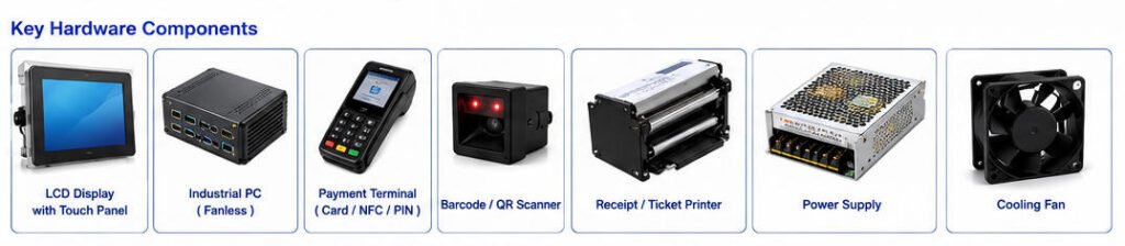
14. Common Structural Problems and Solutions
Problem 1: The printer frequently jams
Possible causes:
- Paper exit is not aligned with the cabinet opening
- Output slot is too narrow
- Paper bends sharply after leaving the cutter
- Paper roll is installed incorrectly
- Internal cable interferes with the paper path
Recommended action:
Open the service door, inspect the complete paper path, and test the printer outside the cabinet. If it works correctly outside the kiosk, adjust the printer bracket or output guide.
Problem 2: USB devices disconnect randomly
Possible causes:
- Insufficient USB power
- Low-quality or excessively long cables
- Loose connectors
- Electromagnetic interference
- Unpowered USB hub
- Unstable computer power supply
Recommended action:
Test each device directly on the computer, remove unnecessary extension cables, and use an industrial powered USB hub where appropriate.
Problem 3: The cabinet becomes too hot
Possible causes:
- Blocked air vents
- Fan failure
- Incorrect fan direction
- Dust accumulation
- High-power components installed too closely
- Insufficient ventilation area
Recommended action:
Clean filters, confirm fan operation and airflow direction, measure internal temperature, and review the component layout.
Problem 4: The touchscreen produces false inputs
Possible causes:
- Grounding problem
- Moisture or contamination on the glass
- Touch-controller interference
- Excessive glass thickness
- Mechanical pressure on the touch sensor
- Incorrect controller settings
Recommended action:
Clean and dry the glass, verify grounding, inspect the mounting pressure, and test the touch assembly outside the cabinet.
Problem 5: Maintenance takes too long
Possible causes:
- Devices installed behind unrelated modules
- Cables not labeled
- Insufficient door opening
- No removable mounting plates
- Connectors positioned against the cabinet wall
Recommended action:
Review service frequency and redesign the internal mounting order so that high-maintenance components are reached first.
15. Pre-Production Hardware Structure Checklist
Before approving a kiosk for production, confirm the following.
Mechanical
- Is the kiosk stable in its final configuration?
- Are all heavy devices securely supported?
- Can the unit be anchored where required?
- Are hinges and locks suitable for repeated use?
- Are there sharp edges inside the service area?
Display and Interaction
- Is the screen height suitable for intended users?
- Is the touch response reliable through the front glass?
- Is the display visible under expected lighting conditions?
- Are the scanner and payment-terminal angles practical?
Electrical
- Is the total power budget documented?
- Is protective grounding installed correctly?
- Are AC and signal cables appropriately separated?
- Are fuses and protection devices accessible?
- Are voltage labels clearly marked?
Peripheral Integration
- Are all selected devices tested with the target operating system?
- Are sufficient USB, serial, and network ports available?
- Can paper and consumables be replaced easily?
- Can every peripheral be removed without dismantling the full kiosk?
Thermal Management
- Is there a clear intake and exhaust path?
- Are fans and filters accessible?
- Has the final configuration been tested with the door closed?
- Has operation been verified under expected ambient conditions?
Serviceability
- Are cables labeled at both ends?
- Are common replacement parts easy to reach?
- Are service instructions available?
- Are spare ports and mounting space available for future changes?
16. Planning a Custom Kiosk Hardware Structure
A custom kiosk should begin with an application and hardware requirement document rather than with an enclosure appearance.
The project team should define:
- Intended kiosk workflow
- Installation environment
- Screen size and orientation
- Operating system
- Computer-performance requirements
- Required peripherals
- Payment-terminal model
- Network method
- Power input
- Accessibility requirements
- Maintenance method
- Branding requirements
- Expected production quantity
After these requirements are confirmed, the enclosure dimensions, device brackets, cable routes, cooling system, service doors, and installation base can be designed around the actual hardware.
AONKIOSK provides custom kiosk hardware manufacturing for projects requiring enclosure design, component integration, internal-layout engineering, prototype verification, small-batch production, or volume manufacturing.
17. AONKIOSK Hardware Engineering Approach
AONKIOSK focuses on the design and manufacturing of complete self-service kiosk hardware, including enclosures, touchscreen displays, embedded computing platforms, payment-device mounts, printers, scanners, communication modules, and application-specific peripherals.
Our hardware-engineering process can include:
- Requirement analysis
- Industrial and mechanical design
- Internal component layout
- Peripheral compatibility verification
- Thermal and cable-management planning
- Prototype production
- Functional testing
- Structural optimization
- Batch assembly and quality inspection
AONKIOSK primarily provides the physical kiosk platform and hardware integration. Customers and system partners can install their preferred kiosk applications, middleware, payment software, POS software, or backend systems.
Conclusion
The hardware structure of a kiosk determines much more than its external appearance. It affects device compatibility, user accessibility, heat dissipation, wiring reliability, security, maintenance time, transportation safety, and the ability to upgrade the kiosk later.
A practical kiosk structure should provide:
- A strong and stable enclosure
- A correctly positioned touch display
- Sufficient computing and I/O capacity
- Properly aligned peripheral devices
- Safe electrical distribution
- Effective cooling and ventilation
- Organized cable routing
- Secure but convenient maintenance access
When troubleshooting a kiosk, inspect the complete structure rather than evaluating each component in isolation. A printer problem may be caused by its paper path, a touchscreen problem may originate from grounding, and a computer shutdown may be related to airflow or power distribution.
For project-specific diagnostics, installation guidance, or hardware-integration questions, visit AONKIOSK technical support.