





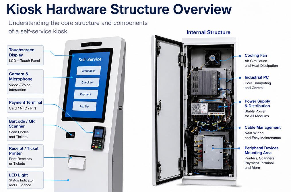
Un kiosque en libre-service n'est pas simplement un écran tactile installé dans une armoire métallique. Il s'agit d'une plateforme matérielle complète dans laquelle l'enceinte, l'affichage, le système informatique, le système d'alimentation, les interfaces de communication, les périphériques, les composants de refroidissement et la structure de maintenance doivent fonctionner ensemble.
Comprendre la structure matérielle du kiosque est important pour les intégrateurs de systèmes, les développeurs de logiciels, les distributeurs d'équipements, les ingénieurs de projet et les utilisateurs finaux. Une structure bien conçue facilite l'installation, l'intégration, la maintenance, le dépannage et la mise à niveau du kiosque tout au long de sa durée de vie.
Ce guide de base de connaissances explique comment les couches physiques et électroniques d'un kiosque sont organisées, comment les principaux modules se connectent et ce qui doit être vérifié lors de la planification ou de la maintenance d'un terminal en libre-service commercial.
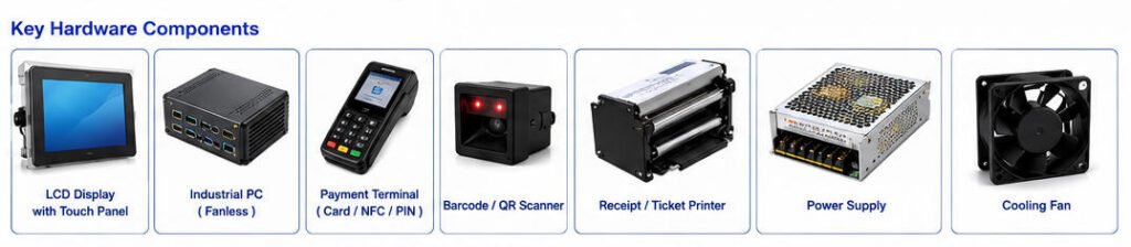
Pour une liste détaillée des dispositifs individuels, reportez-vous à notre guide sur la principaux composants d'une borne libre-service.
1. Qu'est-ce qu'une structure matérielle de kiosque ?
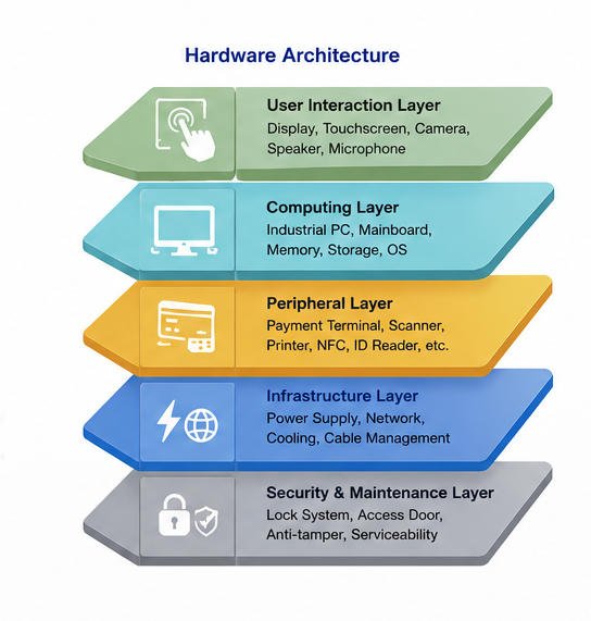
Une structure matérielle de kiosque est l'architecture physique et électronique qui prend en charge toutes les fonctions du kiosque.
Elle comprend normalement six couches interconnectées :
- Enceinte mécanique
- Couche d'affichage et d'interaction utilisateur
- Couche de calcul et de contrôle
- Couche périphérique et de transaction
- Couche d'alimentation, de réseau et de gestion thermique
- Couche de sécurité et de maintenance
Ces couches ne doivent pas être conçues indépendamment. Les dimensions de l'enceinte affectent la position de l'affichage, le flux d'air interne, le chemin du papier de l'imprimante, le routage des câbles, l'accès de maintenance et la méthode d'installation.
De même, les périphériques sélectionnés déterminent le nombre de connexions USB, série, LAN, audio et d'alimentation requises depuis l'ordinateur et le système interne de distribution d'énergie.
Un kiosque fiable dépend donc d'une ingénierie coordonnée en mécanique, en électricité et en intégration.
2. Architecture matérielle simplifiée du kiosque
Un kiosque en libre-service typique peut être représenté par la structure suivante :
Enceinte du kiosqueLa configuration exacte varie selon l'application du kiosque. Un kiosque de commande en restauration peut nécessiter un terminal de paiement, un scanner QR et une imprimante de reçus, tandis qu'un kiosque d'enregistrement hôtelier peut également nécessiter un lecteur de passeport, une caméra, un distributeur de cartes-clés et un dispositif de signature.
3. Structure de l'enceinte mécanique
L'enceinte est la fondation structurelle du kiosque. Elle supporte l'écran et les dispositifs internes tout en protégeant les composants électriques des utilisateurs, des impacts accidentels, de la poussière, de l'accès non autorisé et de l'exposition environnementale.
3.1 Matériaux d'enceinte courants
Les enceintes de kiosques commerciaux sont généralement fabriquées à partir de :
- Acier laminé à froid
- Acier inoxydable
- Alliage d’aluminium
- Verre trempé
- Plastiques techniques pour certains couvercles ou pièces de finition
L'acier laminé à froid est fréquemment utilisé pour les kiosques intérieurs au sol car il offre un équilibre pratique entre résistance, fabricabilité, qualité de surface et coût.
L'acier inoxydable peut être sélectionné pour les environnements humides, corrosifs, de restauration, médicaux ou semi-extérieurs. L'aluminium peut réduire le poids mais peut nécessiter un renforcement supplémentaire selon les dimensions du kiosque et la disposition de montage.
3.2 Cadre interne et panneaux extérieurs
Une enceinte de kiosque comprend normalement deux groupes structurels.
Le cadre interne supporte la charge mécanique principale. Il maintient l'affichage, l'ordinateur, l'imprimante, l'alimentation électrique, le scanner, le dispositif de paiement, les ventilateurs et les composants de gestion des câbles.
Le panneaux extérieurs fournissent l'apparence visible du produit et empêchent l'accès direct aux composants internes.
La séparation du cadre de support des panneaux décoratifs peut simplifier l'assemblage et permettre de modifier les panneaux de marque sans reconcevoir la structure interne complète.
3.3 Structures d'installation
Les formats d'installation courants comprennent :
- Kiosque au sol
- Kiosque de comptoir
- Terminal de bureau
- Kiosque mural
- Kiosque encastré ou intégré au mur
- Kiosque mobile avec roulettes verrouillables
- Kiosque extérieur ou semi-extérieur
Un kiosque au sol doit normalement inclure une base large et stable ainsi que des trous de fixation appropriés. Dans les environnements publics, l'ancrage de la base au sol peut être nécessaire pour réduire le basculement ou le déplacement non autorisé.
Les modèles muraux nécessitent la vérification de la structure du mur, de la capacité de charge du support, de la position d'entrée des câbles et de l'espace de maintenance.
3.4 Vérifications de conception mécanique
Avant la production, les ingénieurs doivent vérifier :
- Centre de gravité
- La stabilité de la base
- Résistance de support de l'écran
- Déformation de la porte
- Charge sur les charnières
- Espace de chargement du papier d'imprimante
- Trajet de retrait des périphériques
- Rayon de courbure des câbles
- Ouvertures de ventilation
- Charges de transport et d'emballage
Un kiosque peut sembler stable sur un plan CAO, mais devenir déséquilibré après l'installation d'une imprimante lourde, d'un module de caisse ou d'un grand terminal de paiement. L'évaluation structurelle doit donc être effectuée avec la configuration matérielle finale.
4. Assemblage de l'écran et de l'écran tactile
L'assemblage de l'écran constitue l'interface principale entre le kiosque et l'utilisateur. Il comprend généralement un panneau LCD, un capteur tactile, un verre de protection, un contrôleur d'affichage, un cadre de montage, ainsi que les câbles de signal et d'alimentation associés.
4.1 Écran commercial
Les écrans de kiosque sont généralement sélectionnés en fonction des critères suivants :
- La taille de l'écran
- Résolution
- Luminosité
- Angle de vision
- Orientation
- Température de fonctionnement
- Durée de vie du rétroéclairage
- Exigences de fonctionnement continu
Les tailles d'écran courantes pour kiosques vont des panneaux compacts de 15,6 pouces aux écrans commerciaux de 21,5 pouces, 27 pouces, 32 pouces et plus.
Les kiosques intérieurs peuvent fonctionner efficacement avec une luminosité standard, tandis que les kiosques installés près de fenêtres ou dans des environnements à forte lumière ambiante peuvent nécessiter un panneau à haute luminosité.
4.2 Technologie tactile
Le tactile capacitif projeté, communément appelé tactile PCAP, est largement utilisé dans les kiosques modernes car il prend en charge une interaction multitouch réactive et une surface en verre plane.
Le tactile infrarouge peut être sélectionné pour les écrans plus grands ou les applications nécessitant un comportement tactile alternatif.
Le contrôleur tactile communique généralement avec l'ordinateur du kiosque via USB. Le signal d'image LCD peut utiliser HDMI, DisplayPort, eDP, LVDS ou une autre interface selon la conception du système.
4.3 Verre de protection et montage
Le verre frontal offre une surface d'interaction nettoyable et contribue à protéger l'écran.
Les considérations techniques comprennent :
- Épaisseur du verre
- Traitement des bords
- Dureté de surface
- Le traitement antireflet
- Exigences de liaison optique
- Sensibilité tactile à travers le verre
- Sélection du joint ou de l'adhésif
- Accessibilité au remplacement
Le support d'écran doit maintenir le panneau de manière sécurisée sans exercer une pression excessive sur le cadre LCD. Une force de montage inégale peut provoquer une distorsion du panneau, des fuites de lumière ou des problèmes de fiabilité à long terme.
Symptômes courants de l'écran
| Symptôme | Cause matérielle possible |
|---|---|
| L'écran n'affiche aucune image | Câble d'écran desserré, source d'entrée incorrecte, panne d'alimentation de l'écran |
| Le tactile ne répond pas | Câble USB déconnecté, problème de pilote tactile, défaillance du contrôleur |
| La position tactile est inexacte | Problème d'étalonnage, résolution incompatible, interférence du verre |
| L'écran scintille | Alimentation instable, câble de signal desserré, contrôleur d'affichage endommagé |
| L'écran est trop sombre | Réglage de luminosité incorrect, dégradation du rétroéclairage, spécification de panneau inadaptée |
Débranchez toujours le kiosque de l'alimentation secteur avant d'ouvrir le boîtier ou de reconnecter les câbles d'affichage internes.
5. Structure de calcul et de contrôle
Le système informatique traite les entrées utilisateur, exécute l'application du kiosque, communique avec les systèmes backend et contrôle les périphériques connectés.
Selon les exigences du projet, le kiosque peut utiliser :
- Mini PC industriel
- Fanless embedded computer
- x86 motherboard
- ARM-based Android mainboard
- Panel PC
- 3 Planification de la capacité des entrées/sorties
2 Imprimante de reçus et de tickets
The computing layer normally contains:
- Processor
- RAM
- SSD, eMMC, or other storage
- La sortie graphique
- Ports USB
- Ethernet interface
- Serial ports
- Audio interface
- Module Wi-Fi ou cellulaire
- Image du système d'exploitation
Windows is frequently used where broad peripheral-driver support is required. Android may be suitable for streamlined touch applications, while Linux can be used for customized embedded deployments.
The hardware platform should be selected according to the software workload rather than screen size alone.
Applications involving video playback, computer vision, multiple displays, real-time analytics, or advanced user interfaces may require more processing power than basic ticketing or information-query applications.
5.2 Industrial PC Placement
The computer should be positioned where it:
- Receives adequate airflow
- Remains accessible for maintenance
- Does not block paper replacement
- Is protected from liquid entry
- Allows convenient cable connection
- Can be replaced without removing unrelated modules
Mounting the computer behind several fixed devices may reduce cabinet size, but it can significantly increase service time.
5.3 I/O Capacity Planning
A common integration mistake is underestimating the number and type of ports required.
Before finalizing the computer, prepare an interface list:
| Dispositif | Typical Interface |
| Contrôleur tactile | USB |
| Scanner de codes-barres | USB or RS232 |
| Imprimante de reçus | USB, RS232, or Ethernet |
| Lecteur NFC | USB or serial |
| Terminal de paiement | USB, serial, or Ethernet |
| Caméra | USB |
| Écran | HDMI, DisplayPort, LVDS, or eDP |
| La connexion réseau | Ethernet, Wi-Fi, or cellular |
| Service sensor | GPIO, USB, or serial |
USB hubs may be used, but powered industrial hubs are preferable when several devices require stable current or continuous communication.
6. Peripheral Integration Structure
Peripheral devices allow the kiosk to perform application-specific tasks. They should be arranged according to the user workflow, internal clearance, device communication requirements, and maintenance frequency.
6.1 Barcode and QR Scanner
A barcode or QR scanner may be used to read:
- Les codes-barres de produits
- Les codes de paiement mobile
- Les codes de fidélité
- Les billets électroniques
- Numéros de commande
- Identity documents
The scanner window should provide a suitable reading angle and should not be obstructed by the cabinet edge.
Ambient light, reflective glass, scanner depth, focal distance, and the expected code size should be evaluated during prototype testing.
6.2 Receipt and Ticket Printer
Thermal printers require careful structural planning because they include moving paper, a paper roll, a cutter, sensors, and a paper-exit path.
L'enceinte doit fournir :
- Sufficient paper-roll clearance
- Easy paper replacement
- A direct paper-output path
- Access to the cutter and print head
- Espace pour le mouvement des câbles
- Protection contre les utilisateurs tirant sur les composants internes
Une sortie papier mal alignée peut provoquer des bourrages papier fréquents, même lorsque l’imprimante elle-même fonctionne correctement.
6.3 Terminal de paiement
L’intégration du terminal de paiement peut impliquer :
- Insertion de carte
- Paiement sans contact par NFC
- Lecture de piste magnétique
- La saisie du code PIN
- Paiement par code QR
- Paiement par portefeuille mobile
Le terminal de paiement doit être monté à une hauteur et un angle confortables. Sa fente pour carte, sa zone NFC, son clavier, son écran et ses fonctions d’accessibilité doivent rester dégagés.
Les dispositifs de paiement sont souvent fournis ou certifiés par des prestataires de paiement tiers. La structure du kiosque doit donc être conçue autour du modèle de terminal sélectionné plutôt qu’autour d’une taille approximative de l’appareil.
Pour les configurations orientées transactions, voir AONKIOSK’s les bornes de vente au détail et de paiement.
6.4 Modules applicatifs optionnels
Selon le secteur d’activité, un kiosque peut également intégrer :
- Lecteur RFID
- Scanner de passeport
- Lecteur de carte d’identité
- Lecteur d'empreintes digitales
- Caméra de reconnaissance faciale
- Scanner de documents
- Distributeur de cartes
- Encodeur de cartes à clé
- Accepteur de billets
- Distributeur de pièces
- Recycleur de billets
- Imprimante d'étiquettes
- Tablette de signature
- Module de pesage
- Indicateur d’état à LED
Chaque dispositif supplémentaire affecte la taille de l’enceinte, le poids, la consommation électrique, la génération de chaleur, les exigences en ports de communication, les pilotes logiciels et les procédures de maintenance.
7. Alimentation électrique et distribution
La structure d’alimentation convertit l’entrée CA du bâtiment en niveaux de tension requis par l’ordinateur, l’écran, l’imprimante, le scanner, les équipements réseau, les ventilateurs et autres modules.
Une disposition interne typique peut inclure :
- Entrée d’alimentation CA
- Interrupteur principal d'alimentation
- Fusible ou protection de circuit
- Filtre CEM
- Dispositif de protection contre les surtensions
- Borniers de distribution CA
- Alimentations CA-CC
- Panneau de distribution CC
- Connexions de mise à la terre
- Alimentation sans interruption optionnelle
7.1 Budget de puissance
La puissance nominale totale de tous les dispositifs internes doit être calculée avant de sélectionner l’alimentation électrique.
Le calcul doit inclure :
- Consommation de pointe de l’ordinateur
- Consommation de l’écran et du rétroéclairage
- Charge de pointe de l’imprimante lors de l’impression et de la découpe
- Consommation du terminal de paiement
- Consommation du scanner et de la caméra
- Ventilateurs de refroidissement
- Modules réseau
- Capacité de réserve pour une expansion future
Les imprimantes et les modules électromécaniques peuvent créer de courtes charges de pointe. La sélection d’une alimentation basée uniquement sur la consommation moyenne peut entraîner des redémarrages aléatoires ou des déconnexions de dispositifs.
7.2 Mise à la terre
Les enceintes métalliques des kiosques doivent utiliser une mise à la terre de protection appropriée.
Les connexions de mise à la terre doivent être sécurisées, clairement identifiées et conçues de sorte que les portes ou panneaux amovibles restent correctement reliés lorsque requis.
Le câblage d’alimentation doit être séparé des câbles de signaux basse tension lorsque cela est pratique afin de réduire les interférences électriques.
7.3 Dépannage électrique
Si le kiosque complet ne s’allume pas, vérifiez les éléments suivants dans l’ordre :
- Confirmez que la prise externe est alimentée.
- Vérifiez le câble d'alimentation et la connexion d'entrée.
- Vérifiez la position de l'interrupteur principal.
- Inspectez le fusible ou le dispositif de protection du circuit.
- Vérifiez si l'alimentation interne dispose d'un indicateur d'entrée.
- Mesurez la sortie continue uniquement avec un équipement approprié et du personnel qualifié.
- Déconnectez les périphériques optionnels afin d'identifier une branche éventuellement surchargée ou en court-circuit.
Ne contournez pas un fusible, une connexion de mise à la terre ou un composant de protection lors du dépannage.
8. Gestion thermique et ventilation
De la chaleur est générée par le processeur, le rétroéclairage de l'écran, les alimentations, les imprimantes, les modules cellulaires et autres composants électroniques.
Sans une structure de gestion thermique adaptée, les températures internes peuvent dépasser la plage de fonctionnement des composants.
Les méthodes courantes de contrôle thermique comprennent :
- La convection naturelle
- Refroidissement par air forcé
- Entrées d'air filtrées
- Ventilateurs d'extraction
- Dissipateurs thermiques
- Ordinateurs industriels sans ventilateur
- Des ventilateurs à contrôle de température
- Climatisation pour bornes extérieures spécialisées
8.1 Conception du flux d'air
L'air doit entrer par une zone inférieure ou plus froide et sortir par une zone supérieure ou plus chaude.
Les câbles, rouleaux de papier, plaques de montage et alimentations ne doivent pas obstruer le chemin du flux d'air.
Les ventilateurs doivent être positionnés de manière à évacuer la chaleur du boîtier plutôt qu'à faire circuler de l'air chaud dans un compartiment fermé.
8.2 Considérations de maintenance
Les filtres de ventilation peuvent accumuler de la poussière et doivent être accessibles pour un nettoyage périodique.
Les symptômes courants de surchauffe comprennent :
- Arrêt inattendu de l'ordinateur
- Gel de l'application
- Instabilité de l'affichage
- Erreurs de communication de l'imprimante
- Bruit du ventilateur
- Une durée de vie réduite des composants
Si la borne fonctionne normalement porte ouverte mais tombe en panne après fermeture de la porte, une restriction du flux d'air ou une température interne excessive doit être examinée.
9. Gestion interne des câbles
La gestion des câbles a un effet direct sur la fiabilité et l'efficacité de la maintenance.
Une borne peut contenir des câbles secteur, des câbles continus, des câbles USB, des câbles série, des câbles Ethernet, des câbles d'affichage, des câbles d'antenne, des câbles audio et des fils de capteurs.
Un bon acheminement des câbles doit :
- Séparer les câbles d'alimentation et les câbles de signal
- Éviter les bords métalliques tranchants
- Maintenir des rayons de courbure appropriés
- Empêcher les câbles de pénétrer dans les pales des ventilateurs
- Empêcher toute interférence avec le papier de l'imprimante
- Permettre l'ouverture des portes sans tirer sur les connecteurs
- Utiliser des étiquettes aux deux extrémités des câbles
- Prévoir un soulagement de tension
- Réserver de l'espace pour les travaux de maintenance futurs
Les serre-câbles ne doivent pas être serrés au point d'endommager l'isolation ou de déformer les câbles de signal sensibles.
Les connecteurs exposés aux vibrations ou aux mouvements répétés des portes peuvent nécessiter des fixations de verrouillage, des clips ou un soulagement de tension supplémentaire.
Étiquettes de câbles recommandées
Un système d'étiquetage pratique peut identifier :
- Nom du dispositif
- Type d'interface
- Port de destination
- Tension
- Numéro de câble
- Informations de remplacement ou de maintenance
Par exemple :
P03 – Imprimante de reçus – USB – Port PC 4Des étiquettes de câbles cohérentes réduisent le temps de dépannage et aident à prévenir les reconnexions incorrectes après une intervention de maintenance.
10. Porte, serrure et structure de maintenance
Les bornes commerciales nécessitent un accès de maintenance, mais l’équipement interne ne doit pas être accessible aux utilisateurs ordinaires.
Une borne typique peut comprendre des zones de service distinctes pour :
- L’ordinateur et l’électronique de commande
- L’imprimante et les consommables
- Dispositif de paiement
- Le module de traitement des espèces
- Les composants de distribution électrique
La séparation de ces zones peut améliorer la sécurité et permettre au personnel de remplacer le papier de l’imprimante sans accéder aux sections de paiement ou électriques.
10.1 Conception de la porte de service
Une porte de service doit offrir :
- Un angle d’ouverture adéquat
- Des charnières fiables
- Des serrures adaptées
- Un mécanisme de retenue de porte
- Un câblage interne protégé
- Aucun bord tranchant exposé
- Un accès pratique aux dispositifs fréquemment entretenus
Le chemin de remplacement est aussi important que l’ouverture d’accès visible. Un composant peut être visible à travers la porte mais néanmoins impossible à retirer si un autre support le bloque.
10.2 Montage modulaire
Les imprimantes, ordinateurs, scanners et alimentations électriques peuvent être installés sur des plaques amovibles ou des supports coulissants.
Le montage modulaire facilite :
- L’assemblage de la borne
- Le remplacement des dispositifs défectueux
- La mise à niveau du matériel
- La production en série
- Le maintien d’un positionnement cohérent des dispositifs
Le module doit inclure suffisamment de mou de câble pour la maintenance sans permettre aux câbles d’interférer avec les pièces mobiles.
11. Structure de sécurité
La sécurité matérielle des bornes comprend à la fois la protection physique et la protection de la plateforme électronique.
Les mesures physiques peuvent inclure :
- Des fixations dissimulées
- Des portes d’accès verrouillables
- Charnières renforcées
- Ancrage au sol
- Des supports de sécurité internes
- Des supports de terminal de paiement protégés
- Interrupteurs anti-intrusion
- Un accès USB restreint
- Vis de sécurité
L’enceinte doit empêcher les utilisateurs d’atteindre les interrupteurs d’alimentation, les ports informatiques, les dispositifs de stockage, les câbles réseau ou le câblage périphérique.
Les ouvertures de ventilation doivent être conçues de manière à ce que les utilisateurs ne puissent pas insérer d’objets et entrer en contact avec des pièces sous tension ou sensibles.
Le niveau de protection requis dépend de l’environnement d’installation. Une borne de restaurant supervisée présente des exigences de sécurité différentes de celles d’un terminal de paiement sans surveillance dans une station de transport.
12. Structure d’accessibilité et d’ergonomie
La structure matérielle affecte la capacité des utilisateurs à voir, atteindre, entendre et utiliser confortablement la borne.
Les facteurs de conception importants incluent :
- La hauteur de l’écran tactile
- L’angle de vision de l’écran
- La distance d’atteinte
- La position du terminal de paiement
- La position du scanner
- La hauteur de sortie de l’imprimante
- Espace d'approche pour fauteuil roulant
- Emplacement de sortie audio
- Confidentialité lors de la saisie du code PIN
- Visibilité des instructions et des indicateurs d'état
L'accessibilité doit être prise en compte dès le début de la conception mécanique. Déplacer l'écran tactile ou le terminal de paiement après l'achèvement de l'outillage et des supports internes peut nécessiter une refonte majeure.
Les dimensions finales doivent être évaluées par rapport aux exigences d'accessibilité applicables sur le marché de déploiement cible.
13. Sélection de la structure selon l'application
Différentes applications de bornes nécessitent différentes configurations internes.
Borne de commande en libre-service pour restaurant
Structure typique :
- Écran tactile de 21,5 à 32 pouces
- PC intégré ou carte Android
- Terminal de paiement
- Lecteur de code QR ou de code-barres
- Imprimante de reçus
- Haut-parleur
- Boîtier sur pied ou mural
L'imprimante et le terminal de paiement doivent être facilement accessibles au personnel du restaurant lors des opérations quotidiennes.
Borne de libre-service pour commerce de détail
Structure typique :
- Écran tactile
- Ordinateur POS
- Scanner de codes-barres haute performance
- Terminal de paiement
- Imprimante de reçus
- Balance de sacrage en option
- Système de gestion d'espèces en option
- Caméra de sécurité
Les configurations de vente au détail nécessitent généralement plus d'espace interne, davantage d'interfaces d'E/S et une planification renforcée contre la perte.
Borne d'enregistrement hôtelier
Structure typique :
- Écran tactile
- Scanner de passeport ou de carte d'identité
- Caméra
- Terminal de paiement
- Imprimante de reçus
- Encodeur ou distributeur de cartes-clés
- Tablette de signature en option
Les chemins d'acheminement des documents et des cartes doivent rester accessibles pour le déblocage des bourrages.
Borne d'information et d'orientation
Structure typique :
- Grand écran portrait ou paysage
- Interface tactile
- Ordinateur industriel
- Haut-parleurs
- Caméra ou scanner si nécessaire
- La connexion réseau
Ces bornes peuvent utiliser moins de périphériques de transaction, mais nécessitent une fixation d'écran soignée, une conception thermique adaptée et une stabilité visuelle.
Borne de Ticketing
Structure typique :
- Écran tactile
- Terminal de paiement
- Lecteur de code QR ou de code-barres
- Imprimante de tickets
- Imprimante de reçus
- Lecteur d'identité en option
- Module d'espèces en option
Le chemin du papier et la zone de collecte des tickets doivent être testés avec le matériau de ticket réel.
14. Problèmes structurels courants et solutions
Problème 1 : L'imprimante se bloque fréquemment
Causes possibles :
- La sortie papier n'est pas alignée avec l'ouverture du boîtier
- La fente de sortie est trop étroite
- Le papier se plie brusquement après avoir quitté le dispositif de coupe
- Le rouleau de papier est installé incorrectement
- Un câble interne interfère avec le chemin du papier
Action recommandée :
Ouvrez la porte de service, inspectez l'ensemble du chemin du papier et testez l'imprimante hors du boîtier. Si elle fonctionne correctement à l'extérieur de la borne, ajustez le support de l'imprimante ou le guide de sortie.
Problème 2 : Les périphériques USB se déconnectent de manière aléatoire
Causes possibles :
- Alimentation USB insuffisante
- Câbles de mauvaise qualité ou excessivement longs
- Connecteurs desserrés
- Interférences électromagnétiques
- Concentrateur USB non alimenté
- Alimentation électrique instable de l'ordinateur
Action recommandée :
Testez chaque périphérique directement sur l'ordinateur, retirez les câbles d'extension inutiles et utilisez un concentrateur USB industriel alimenté lorsque cela est approprié.
Problème 3 : Le boîtier devient trop chaud
Causes possibles :
- Évents d'aération obstrués
- Panne du ventilateur
- Direction incorrecte du ventilateur
- La lumière ambiante vive
- Composants haute puissance installés trop rapprochés
- Surface de ventilation insuffisante
Action recommandée :
Nettoyer les filtres, vérifier le fonctionnement du ventilateur et le sens du flux d'air, mesurer la température interne et examiner la disposition des composants.
Problème 4 : L'écran tactile génère des saisies erronées
Causes possibles :
- Problème de mise à la terre
- Humidité ou contamination sur la vitre
- Interférence du contrôleur tactile
- Épaisseur excessive de la vitre
- Pression mécanique sur le capteur tactile
- Paramètres incorrects du contrôleur
Action recommandée :
Nettoyer et sécher la vitre, vérifier la mise à la terre, inspecter la pression de montage et tester l'ensemble tactile hors de l'armoire.
Problème 5 : La maintenance prend trop de temps
Causes possibles :
- Dispositifs installés derrière des modules sans rapport
- Câbles non étiquetés
- Ouverture de porte insuffisante
- Absence de plaques de montage amovibles
- Connecteurs positionnés contre la paroi de l'armoire
Action recommandée :
Réviser la fréquence de maintenance et repenser l'ordre de montage interne afin que les composants nécessitant une maintenance fréquente soient accessibles en premier.
15. Liste de contrôle de la structure matérielle en pré-production
Avant d'approuver un kiosque pour la production, vérifier les points suivants.
Mécanique
- Le kiosque est-il stable dans sa configuration finale ?
- Tous les dispositifs lourds sont-ils solidement supportés ?
- L'unité peut-elle être ancrée là où cela est requis ?
- Les charnières et les serrures sont-elles adaptées à une utilisation répétée ?
- Y a-t-il des bords tranchants à l'intérieur de la zone de service ?
Affichage et interaction
- La hauteur de l'écran est-elle adaptée aux utilisateurs ciblés ?
- La réponse tactile est-elle fiable à travers la vitre avant ?
- L'affichage est-il visible dans les conditions d'éclairage prévues ?
- Les angles du scanner et du terminal de paiement sont-ils pratiques ?
Électrique
- Le budget de puissance total est-il documenté ?
- La mise à la terre de protection est-elle correctement installée ?
- Les câbles CA et les câbles de signal sont-ils correctement séparés ?
- Les fusibles et les dispositifs de protection sont-ils accessibles ?
- Les étiquettes de tension sont-elles clairement marquées ?
Intégration des périphériques
- Tous les dispositifs sélectionnés ont-ils été testés avec le système d'exploitation cible ?
- Des ports USB, série et réseau suffisants sont-ils disponibles ?
- Le papier et les consommables peuvent-ils être remplacés facilement ?
- Chaque périphérique peut-il être retiré sans démonter l'ensemble du kiosque ?
Gestion thermique
- Existe-t-il un chemin d'admission et d'évacuation clair ?
- Les ventilateurs et les filtres sont-ils accessibles ?
- La configuration finale a-t-elle été testée porte fermée ?
- Le fonctionnement a-t-il été vérifié dans les conditions ambiantes prévues ?
Maintenabilité
- Les câbles sont-ils étiquetés aux deux extrémités ?
- Les pièces de rechange courantes sont-elles faciles à atteindre ?
- Des instructions de maintenance sont-elles disponibles ?
- Des ports de rechange et de l'espace de montage sont-ils disponibles pour de futures modifications ?
16. Planification de la structure matérielle d'un kiosque personnalisé
Un kiosque personnalisé doit commencer par un document relatif aux exigences applicatives et matérielles, plutôt que par l’apparence de son enveloppe.
L’équipe projet doit définir :
- Le flux de travail prévu du kiosque
- L'environnement d'installation
- La taille et l'orientation de l'écran
- Le système d’exploitation
- Les exigences de performance informatique
- Périphériques requis
- Modèle du terminal de paiement
- Méthode de connexion réseau
- Alimentation électrique
- Exigences d'accessibilité
- Méthode de maintenance
- Exigences d'image de marque
- La quantité de production attendue
Une fois ces exigences confirmées, les dimensions de l’enveloppe, les supports de dispositifs, les chemins de câbles, le système de refroidissement, les portes de service et la base d’installation peuvent être conçus autour du matériel réel.
AONKIOSK fournit Fabrication matérielle de kiosques personnalisés Pour les projets nécessitant la conception d’enveloppes, l’intégration de composants, l’ingénierie de l’agencement interne, la vérification de prototypes, la production en petite série ou la fabrication en volume.
17. Approche d’ingénierie matérielle d’AONKIOSK
AONKIOSK se concentre sur la conception et la fabrication de systèmes complets Matériel de borne libre-service, y compris les enveloppes, les écrans tactiles, les plateformes informatiques embarquées, les supports de dispositifs de paiement, les imprimantes, les scanners, les modules de communication et les périphériques spécifiques aux applications.
Notre processus d’ingénierie matérielle peut inclure :
- Analyse des exigences
- Conception industrielle et mécanique
- Disposition des composants internes
- Vérification de la compatibilité des périphériques
- Planification thermique et gestion des câbles
- Production du prototype
- Tests fonctionnels
- Optimisation structurelle
- Assemblage par lots et inspection qualité
AONKIOSK fournit principalement la plateforme physique du kiosque et l’intégration matérielle. Les clients et partenaires système peuvent installer leurs applications de kiosque, middleware, logiciels de paiement, logiciels POS ou systèmes backend préférés.
Conclusion
La structure matérielle d’un kiosque détermine bien plus que son apparence extérieure. Elle affecte la compatibilité des dispositifs, l’accessibilité utilisateur, la dissipation thermique, la fiabilité du câblage, la sécurité, le temps de maintenance, la sécurité du transport et la capacité à faire évoluer le kiosque ultérieurement.
Une structure de kiosque pratique doit offrir :
- Une enveloppe robuste et stable
- Un écran tactile correctement positionné
- Une capacité informatique et d’E/S suffisante
- Des périphériques correctement alignés
- Une distribution électrique sûre
- Un refroidissement et une ventilation efficaces
- Un cheminement de câbles organisé
- Un accès de maintenance sécurisé mais pratique
Lors du dépannage d’un kiosque, inspectez la structure complète plutôt que d’évaluer chaque composant isolément. Un problème d’imprimante peut être causé par son chemin de papier, un problème d’écran tactile peut provenir de la mise à la terre, et un arrêt de l’ordinateur peut être lié au flux d’air ou à la distribution électrique.
Pour des diagnostics spécifiques au projet, des conseils d’installation ou des questions d’intégration matérielle, visitez AONKIOSK. page d'assistance technique.