





A wall-mounted kiosk is a self-service terminal installed directly on a structural wall, column, recessed frame, or engineered mounting surface. Compared with a floor-standing kiosk, it occupies less usable floor space and can keep pedestrian routes, service counters, and waiting areas more open.
However, a wall-mounted kiosk is not simply a standard touchscreen placed inside a metal box. Its structure must transfer the complete equipment load safely to the building, maintain an appropriate operating height, protect internal electronics, manage power and data cables, and still allow technicians to access printers, computers, scanners, and payment devices.
This guide explains the main structural components of a wall-mounted kiosk, how the internal hardware is arranged, what must be checked before installation, and how common mechanical and operational problems can be diagnosed.
1. What Is a Wall-Mounted Kiosk?
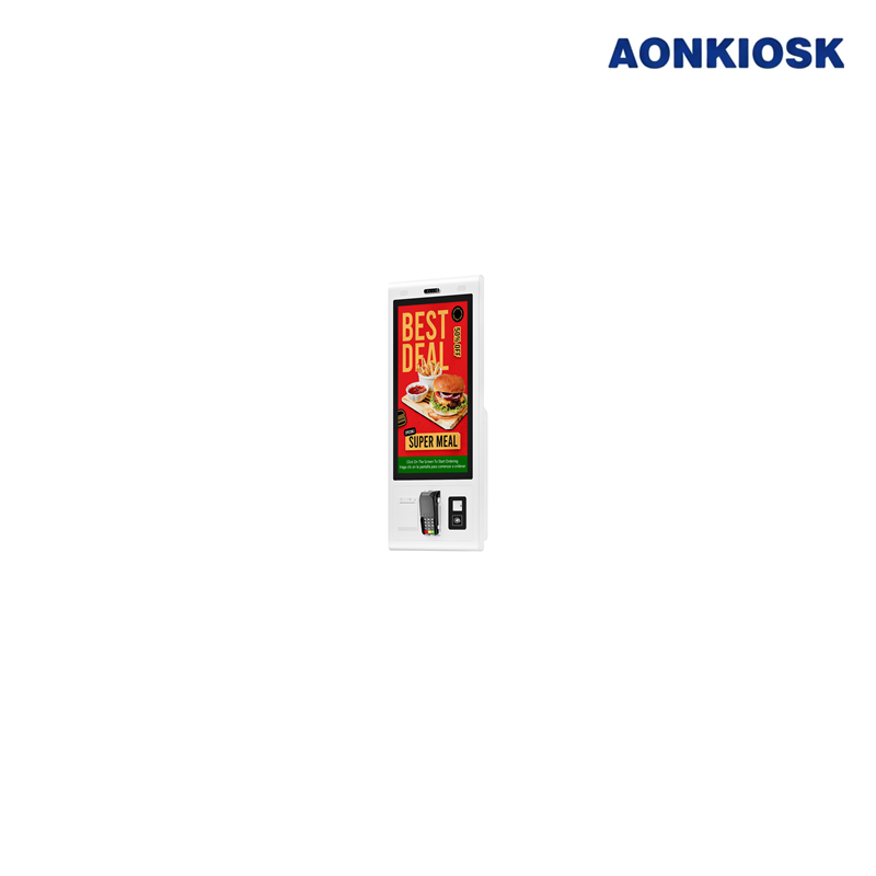
A wall-mounted kiosk is a compact self-service machine whose enclosure is supported by a wall-mounting system rather than a pedestal or floor base.
Depending on the application, the kiosk may include:
- Touchscreen display
- Industrial PC or Android mainboard
- QR or barcode scanner
- NFC reader
- Payment terminal
- Receipt or ticket printer
- Camera
- Speaker and microphone
- Status indicator
- Network and power modules
Wall-mounted kiosks are commonly used for:
- Restaurant self-ordering
- Visitor registration
- Hotel check-in assistance
- Queue ticket issuance
- Product information lookup
- Wayfinding and directories
- Healthcare registration
- Employee self-service
- Bill payment
- Access control
The installation format is particularly useful where floor space is limited or where equipment must remain clear of cleaning routes, shopping carts, luggage, and pedestrian traffic.
For a broader comparison of kiosk formats and components, refer to the Kiosk Hardware Structure Overview.
2. Main Parts of a Wall-Mounted Kiosk Structure
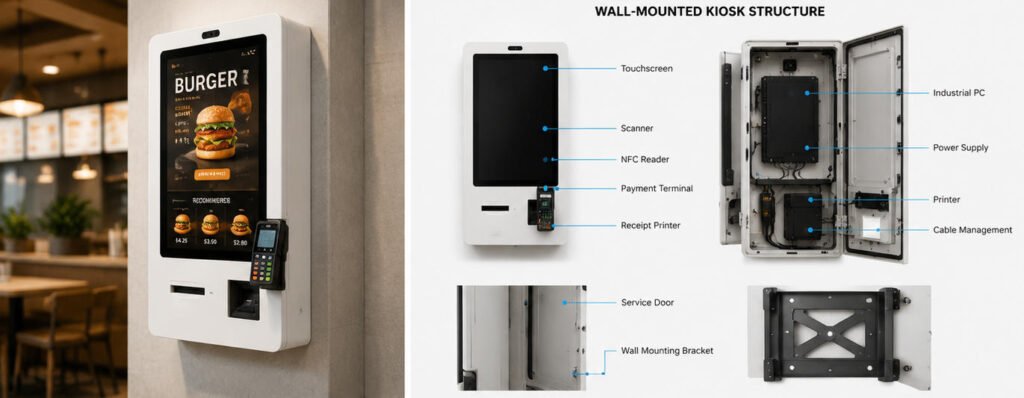
A reliable wall-mounted kiosk normally consists of five structural areas:
- Front operating panel
- Main enclosure
- Internal mounting frame
- Service-access structure
- Wall-mounting assembly
These areas must work together as one mechanical system.
2.1 Front Operating Panel
The front panel is the user-facing section of the kiosk. It supports the touchscreen and provides openings or mounting positions for user-operated peripherals.
A typical front panel may contain:
- Touchscreen opening
- Payment-terminal bracket
- Scanner window
- NFC reading area
- Printer-output slot
- Camera opening
- Speaker holes
- Microphone opening
- Status LEDs
The position of each device should follow the software workflow. Frequently used devices must be visible and reachable without forcing users to stretch, bend excessively, or move between different sides of the kiosk.
The front panel must also remain rigid. Excessive flexing can cause the touchscreen bezel to move, scanner windows to become misaligned, and payment-terminal brackets to loosen during repeated use.
Depending on the industrial design, the panel may be manufactured from cold-rolled steel, stainless steel, aluminum, tempered glass, or a combination of materials. Additional guidance is available in the Kiosk Enclosure Materials: Metal vs Steel Selection Guide.
2.2 Main Enclosure
The enclosure protects the computer, power supply, controllers, cables, and other internal components.
Its depth depends on the installed hardware. A basic information kiosk containing only a display and embedded computer can use a relatively slim enclosure. A transaction kiosk with a printer, payment terminal, scanner, and power adapters requires more internal volume.
The enclosure should provide:
- Sufficient structural rigidity
- Protected cable entry
- Ventilation openings
- Lockable service access
- Internal grounding points
- Peripheral mounting positions
- Space for cable bend radius
- Clearance for component removal
- Protection from unauthorized access
Reducing enclosure depth can improve appearance, but making the cabinet too shallow creates practical problems. Cables may press against the rear cover, printer paper may be difficult to replace, connectors may become damaged, and heat may accumulate behind the display.
Cabinet depth should therefore be determined from the final hardware configuration rather than from appearance alone.
2.3 Internal Mounting Frame
The internal frame supports the touchscreen, computer, printer, power modules, and peripheral brackets.
This frame may be integrated into the enclosure or manufactured as a separate welded or bolted assembly. It transfers internal component loads to the rear mounting structure.
Important frame design considerations include:
- Display weight and center of gravity
- Printer vibration
- Payment-terminal operating force
- Door and hinge loading
- Component replacement paths
- Fastener accessibility
- Cable routing
- Manufacturing tolerances
Heavy devices should be fixed to structural brackets rather than directly to a thin decorative cover. A receipt printer, for example, may generate movement each time paper is cut. Without a rigid bracket, this movement can gradually loosen screws or shift the printer-output alignment.
The internal frame should also separate service areas where possible. Power components, computing hardware, and frequently maintained peripherals do not always need to occupy the same compartment.
2.4 Service Door or Hinged Front Assembly
Technicians need access to the internal hardware for:
- Printer paper replacement
- Jam removal
- Computer replacement
- Cable inspection
- Power-supply maintenance
- Scanner adjustment
- Cleaning
- Software servicing
- Peripheral upgrades
Common access structures include:
- Hinged front panel
- Hinged side door
- Removable rear cover
- Drop-down service panel
- Slide-out internal tray
- Recessed service cabinet
For most wall-mounted kiosks, rear access is limited because the enclosure is installed directly against the wall. Maintenance must therefore be performed from the front, side, top, or bottom.
A hinged front panel is convenient, but its weight must be considered. The hinges, gas springs, support cables, locking points, and opening direction must safely control the panel during maintenance.
Service doors should not swing into busy walkways or obstruct nearby equipment. Technicians should also be able to open the kiosk without removing the entire machine from the wall.
2.5 Wall-Mounting Assembly
The mounting assembly connects the kiosk enclosure to the building structure. It may include:
- Steel wall plate
- Interlocking mounting rails
- VESA-compatible bracket
- Reinforced rear frame
- Security fasteners
- Anti-lift locking points
- Expansion anchors
- Chemical anchors
- Through-bolts
- Secondary safety cable
The selected mounting method must suit the wall material, kiosk weight, operating forces, and local installation requirements.
A wall-mounting bracket should not be rated only for the kiosk’s static weight. It must also resist the forces created when users press the touchscreen, operate a card terminal, pull printed paper, or accidentally lean against the enclosure.
3. Wall Structure and Load Requirements
Before installing a wall-mounted self-service kiosk, the installer must identify what is behind the finished wall surface.
Possible wall constructions include:
- Reinforced concrete
- Solid brick
- Hollow brick
- Concrete block
- Steel framing
- Timber framing
- Gypsum board
- Decorative wall panels
- Glass partitions
A finished wall may look strong while providing little structural support. Gypsum board, thin decorative panels, and lightweight partitions normally cannot support a commercial kiosk without reinforcement.
Suitable reinforcement may require:
- Fixing into concrete or masonry
- Attaching to structural studs
- Installing a steel backing plate
- Adding plywood reinforcement behind the wall
- Building an independent steel support frame
- Using through-bolts and backing plates
The installer should verify:
- Complete kiosk weight
- Weight of all installed peripherals
- Bracket load rating
- Anchor type and size
- Wall material
- Anchor spacing
- Edge distances
- Required safety factor
- User-applied operating force
- Local building and safety requirements
The final kiosk configuration must be evaluated. A sample enclosure fitted only with a touchscreen may weigh substantially less than the production version after a printer, payment device, computer, power supply, and internal steel brackets are added.
4. Screen Height, Viewing Angle and Accessibility
Mounting height is one of the most important wall-mounted kiosk dimensions because it becomes difficult to change after the wall holes, electrical outlets, and cable entries have been completed.
The design should consider:
- Standing users
- Seated users
- Wheelchair users
- Children where relevant
- Screen size
- Portrait or landscape orientation
- Touch target positions
- Payment-terminal height
- Scanner height
- Printer-output position
- Glare and lighting
- User approach space
The center of the display should not automatically be treated as the main reference point. Users normally interact with controls distributed across the screen, and important buttons may appear close to the top or bottom of the interface.
For this reason, the actual software interface should be tested at the intended installation height.
The viewing angle must also be evaluated. A vertically mounted display may create reflections under ceiling lighting, while an excessive downward tilt can reduce readability for taller users. Screen angle, cover-glass treatment, brightness, and ambient lighting should be assessed together.
AONKIOSK commonly configures wall-mounted terminals with commercial touchscreen sizes suited to compact ordering, check-in, and information applications. The appropriate display should be selected according to viewing distance, interface complexity, and available wall area. See How to Select the Right Touchscreen Size for a Self-Service Kiosk for additional guidance.
Accessibility requirements differ between deployment markets and applications. The final dimensions should be reviewed against the standards and regulations applicable at the installation location.
5. Internal Hardware Layout
A wall-mounted enclosure has less internal depth than many floor-standing kiosks, making component placement especially important.
5.1 Touchscreen and Display
The touchscreen assembly usually occupies most of the front surface. It may include:
- LCD panel
- Capacitive or infrared touch sensor
- Cover glass
- Display controller
- Video cable
- USB touch cable
- Mounting brackets
The mounting structure should prevent pressure from being transferred unevenly to the LCD panel or touch sensor.
Adequate clearance must be maintained around connectors. HDMI, DisplayPort, USB, and power connectors should not be sharply bent against the rear enclosure.
For help selecting the touch technology, refer to Touch Screen Types Used in Self-Service Kiosks.
5.2 Industrial Computer or Mainboard
The computing platform is normally positioned behind or beside the display.
Common options include:
- Fanless industrial PC
- Embedded box PC
- Windows mainboard
- Android mainboard
- POS computer
- Single-board computer
The computer should remain accessible without removing the display whenever possible. Technicians may need to replace storage, reconnect cables, access USB ports, reset the system, or exchange the complete computing unit.
The selected location must provide adequate airflow and should not place the computer directly beside high-temperature power supplies without thermal evaluation.
5.3 Printer
Receipt and ticket printers are among the most difficult components to integrate into a slim wall-mounted enclosure.
The structure must allow space for:
- Paper roll
- Paper-loading movement
- Cutter mechanism
- Printed-paper path
- Connector access
- Jam removal
- Roll replacement
- Sensor cleaning
The output slot should align with the printer path and prevent paper from curling back into the enclosure.
Maintenance staff should be able to replace the paper roll without supporting a heavy front door or disconnecting unrelated components.
If large paper rolls, multiple printers, document printing, or frequent servicing are required, a deeper enclosure or partially recessed installation may be more appropriate.
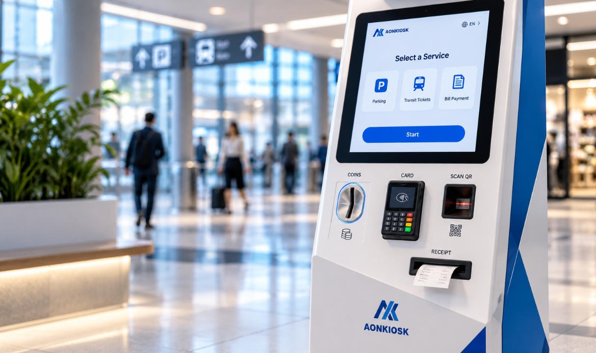
5.4 Scanner, NFC Reader and Payment Terminal
Scanners and payment devices should be positioned according to the transaction sequence.
A typical workflow may be:
- Select a service on the touchscreen.
- Scan a QR code or membership card.
- Confirm the transaction.
- Pay by card or contactless method.
- Collect the printed receipt.
Peripheral positioning should support this sequence naturally.
Scanner windows require correct distance and angle relative to the scan engine. NFC antennas should not be installed directly behind metal unless the reader design provides appropriate isolation. Payment-terminal brackets must resist repeated card insertion, PIN entry, and contactless tapping.
For projects involving retail transactions, compatible configurations can be reviewed under Retail & Payment Kiosks.
6. Power, Data and Cable Routing
Cable planning should be completed before the wall is finished.
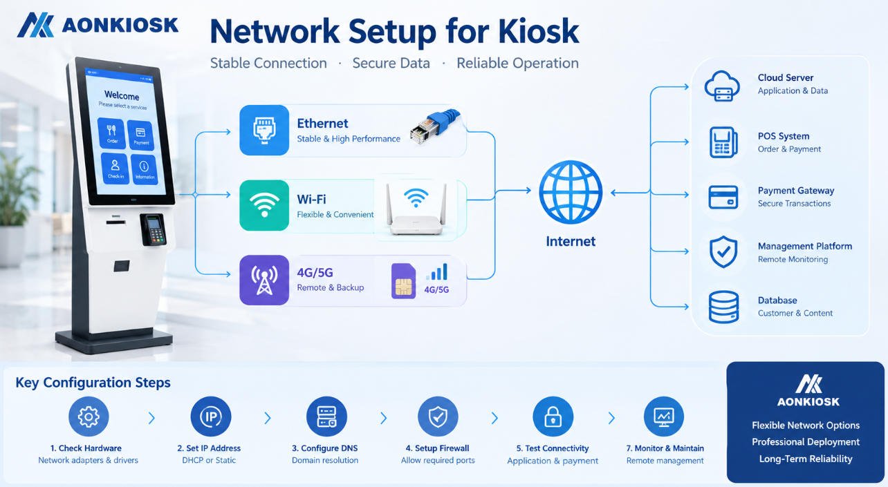
A wall-mounted kiosk may require:
- AC power
- Ethernet
- USB extensions
- Video cables
- Audio cables
- Antenna cables
- Peripheral power
- Alarm or access-control wiring
Common cable-entry methods include:
- Concealed in-wall conduit
- Rear cable entry
- Bottom cable entry
- Surface-mounted cable trunking
- Recessed electrical box
- Flexible metal conduit
Concealed rear entry normally produces the cleanest installation, but the wall outlet and conduit position must align accurately with the kiosk opening.
The cable-entry area should not interfere with the wall bracket. Cables must also have enough service length for the front panel or internal tray to open safely.
Inside the kiosk, power and low-voltage signal cables should be routed neatly and retained with clips, ties, ducts, or strain-relief brackets. Cables should not contact printer cutters, door hinges, sharp sheet-metal edges, ventilation fans, or hot components.
All exposed metal parts should be grounded according to the electrical design. The kiosk should also provide a controlled method for disconnecting power during servicing.
7. Ventilation and Thermal Management
Wall-mounted kiosks often have limited internal air volume and reduced clearance behind the enclosure.
Heat may be generated by:
- LCD backlight
- Industrial computer
- Power supply
- Payment terminal
- Printer
- Charging modules
- Communication equipment
Thermal management options include:
- Passive ventilation openings
- Internal circulation fans
- Filtered air inlets
- Heat-conductive mounting plates
- Low-power fanless computers
- Temperature-controlled fans
- Separation of heat-producing components
Ventilation openings should be positioned so that warm air can rise and leave the enclosure while cooler air enters from below. However, opening size and position must also prevent users from reaching internal wiring or inserting foreign objects.
A kiosk installed inside a recessed wall cavity requires particular attention. The cavity may trap heat even when the enclosure itself contains ventilation holes.
Thermal testing should be conducted with the production-equivalent hardware operating under expected ambient conditions. Testing only the empty enclosure does not confirm that the complete kiosk can operate reliably.
Outdoor or semi-outdoor wall installations require additional environmental protection, sealing, sunlight control, and condensation planning. These applications should be evaluated using the Outdoor Kiosk Requirements Guide.
8. Security Design
Because a wall-mounted kiosk is often installed in public or semi-public locations, users should not be able to access internal electronics or remove the machine from its bracket.
Security features may include:
- Concealed mounting fasteners
- Anti-lift bracket locks
- Lockable service doors
- Security screws
- Reinforced hinges
- Internal cable protection
- Tamper switches
- Protected USB ports
- Restricted power-switch access
- Payment-terminal security brackets
Locks should be positioned where authorized staff can reach them without making them obvious to users.
The mounting rail should prevent the enclosure from being lifted or slid away after installation. A secondary retaining screw or internal bracket can lock the kiosk to the wall plate.
Security requirements should match the application. A supervised restaurant ordering terminal has different risks from an unattended payment kiosk installed in a transportation station.
9. Installation Procedure
The exact installation process depends on the wall and bracket design, but a typical procedure includes the following steps.
Step 1: Confirm the Installation Location
Check:
- User circulation
- Operating height
- Accessibility
- Nearby doors and equipment
- Lighting and reflections
- Maintenance clearance
- Power and network availability
- Emergency-route requirements
Step 2: Inspect the Wall
Identify the wall material and structural support. Do not rely only on the visible surface.
Step 3: Confirm the Final Equipment Weight
Include the enclosure, screen, computer, printer, paper roll, payment device, scanners, power modules, brackets, and cables.
Step 4: Mark the Bracket Position
Use the approved installation drawing or mounting template. Verify horizontal alignment and finished-floor height.
Step 5: Install Suitable Anchors
Use anchors specified for the actual wall structure and design load. Damaged, loose, or incorrectly positioned anchors should not be reused.
Step 6: Install Power and Data Connections
Route cables through the planned entry point while maintaining strain relief and service length.
Step 7: Attach the Wall Plate
Tighten the fasteners evenly and verify that the plate is flat and secure.
Step 8: Mount the Kiosk
This step may require two or more installers, depending on equipment size and weight. Lifting should follow the manufacturer’s handling instructions.
Step 9: Secure the Anti-Lift Lock
Install the retaining fasteners, locking screws, or safety cable that prevents the kiosk from being removed from the bracket.
Step 10: Test the Complete System
Verify:
- Structural stability
- Touchscreen operation
- Network communication
- Printer operation
- Scanner alignment
- Payment-terminal access
- Door and lock operation
- Ventilation
- Cable clearance
- Software workflow
10. Maintenance Requirements
Routine maintenance helps prevent failures caused by dust, loose fasteners, damaged cables, and blocked printer paths.
Recommended checks include:
- Clean the touchscreen and cover glass.
- Inspect scanner and camera windows.
- Remove paper dust from the printer.
- Check paper-roll condition.
- Inspect hinges and gas springs.
- Confirm that locks operate correctly.
- Check mounting fasteners.
- Inspect cable strain relief.
- Remove dust from ventilation openings.
- Confirm that fans operate normally.
- Check for unusual heat or noise.
- Test payment and scanning devices.
- Review system error logs.
The maintenance interval should reflect usage. A high-volume restaurant or transport kiosk may require more frequent printer and touchscreen servicing than a low-traffic information terminal.
11. Common Problems and Troubleshooting
The Kiosk Moves When the Screen Is Pressed
Possible causes:
- Loose wall anchors
- Flexible wall structure
- Insufficient backing reinforcement
- Loose wall plate
- Excessive bracket clearance
- Deformed rear panel
Stop using the kiosk if the mounting system appears unsafe. Inspect the wall, anchors, bracket, and enclosure before returning the machine to service.
The Front Panel Does Not Close Correctly
Check for:
- Cables trapped near the edge
- Paper roll installed incorrectly
- Loose internal bracket
- Misaligned lock
- Bent hinge
- Peripheral extending beyond its mounting area
Do not force the panel closed, as this may damage cables, connectors, or the display.
The Printer Frequently Jams
Possible causes include:
- Incorrect paper type
- Misaligned output slot
- Restricted paper path
- Dirty cutter
- Paper roll installed in the wrong direction
- Insufficient clearance around the printer
Test the printer with the actual production paper and verify that the cabinet output path matches the printer manufacturer’s requirements.
The Kiosk Overheats
Inspect:
- Blocked air vents
- Failed fan
- Dust accumulation
- Excessive ambient temperature
- Inadequate recessed-wall ventilation
- High-power replacement components
- Incorrect power-supply placement
Measure internal temperatures during normal operation rather than relying only on the external cabinet temperature.
Touch Operation Is Unstable
Check:
- Grounding
- USB cable retention
- Electromagnetic interference
- Moisture on the screen
- Damaged cover glass
- Touch-controller connection
- Pressure from the mounting frame
If the problem started after installation, verify that the touchscreen frame was not distorted when the enclosure was tightened to an uneven wall.
Network Connections Disconnect Intermittently
Inspect:
- Ethernet connector retention
- Cable bend radius
- Power stability
- Router or switch status
- Antenna position
- Metal enclosure interference
- Cable damage near the hinge
Wireless antennas may need to be positioned outside heavily shielded sections of the metal enclosure.
12. Wall-Mounted, Recessed or Floor-Standing?
A wall-mounted kiosk is suitable when:
- Floor space is limited.
- The wall can support the equipment.
- The required peripherals fit within a compact enclosure.
- Front or side maintenance is possible.
- Users approach the kiosk from a predictable direction.
A recessed kiosk may be more suitable when:
- A flush architectural appearance is required.
- The wall cavity can provide sufficient depth.
- Rear service access is available.
- Ventilation can be engineered into the wall.
A floor-standing kiosk may be more suitable when:
- The wall cannot support the load.
- Large printers or cash modules are required.
- The kiosk may be relocated.
- More internal expansion space is needed.
- Installation cannot modify the building wall.
The decision should be based on the complete workflow, component list, building conditions, accessibility requirements, and maintenance process—not on appearance alone.
13. Wall-Mounted Kiosk Specification Checklist
Before requesting a quotation or approving a design, define:
- Application and user workflow
- Indoor, semi-outdoor, or outdoor environment
- Screen size and orientation
- Touchscreen technology
- Operating system
- Computing performance
- Printer model and paper size
- Scanner model
- NFC or RFID requirements
- Payment-terminal model
- Camera and audio requirements
- Enclosure material and finish
- Complete product weight
- Wall construction
- Mounting height
- Bracket and anchor requirements
- Cable-entry position
- Ventilation method
- Maintenance-access direction
- Lock and security requirements
- Accessibility requirements
- Certification requirements
- Packaging and installation method
Providing exact peripheral models is important because devices with similar functions may have different dimensions, connectors, ventilation needs, and maintenance paths.
14. AONKIOSK Wall-Mounted Kiosk Engineering
AONKIOSK develops configurable and custom self-service kiosk hardware for ordering, payment, check-in, ticketing, information, retail, hospitality, and public-service applications.
Wall-mounted kiosk customization can include:
- Enclosure dimensions
- Portrait or landscape display
- Touchscreen size
- Wall bracket design
- Internal component layout
- Printer integration
- Scanner and NFC modules
- Payment-terminal brackets
- Camera and audio modules
- Cable-entry positions
- Ventilation design
- Locking and service access
- Surface color and branding
A production-ready design should be evaluated using the actual display, computer, printer, scanner, payment device, and installation method. A prototype allows the project team to verify operating height, interface ergonomics, wall loading, cable routing, thermal performance, maintenance access, and software-hardware compatibility before volume production.
AONKIOSK’s OEM and ODM Self-Service Kiosk Manufacturing service supports projects from requirement evaluation and mechanical design through prototype development, testing, production, quality inspection, and global delivery.
Conclusion
A reliable wall-mounted kiosk depends on more than a compact cabinet. The wall structure, mounting bracket, internal frame, component layout, cable entry, ventilation, accessibility, security, and service method must be engineered as one complete system.
The most important project decisions should be made before the wall is finished and before the kiosk enclosure enters production. Confirm the actual wall construction, complete equipment weight, final peripheral models, mounting height, electrical connections, and maintenance process.
When these factors are validated through engineering review and prototype testing, a wall-mounted self-service kiosk can provide a compact, secure, maintainable, and space-efficient alternative to a floor-standing terminal.