





Un kiosque mural est un terminal en libre-service installé directement sur un mur structurel, une colonne, un cadre encastré ou une surface de montage technique. Par rapport à un kiosque au sol, il occupe moins d'espace au sol utilisable et permet de maintenir les voies piétonnes, les comptoirs de service et les zones d'attente plus dégagés.
Cependant, un kiosque mural n'est pas simplement un écran tactile standard placé dans une boîte métallique. Sa structure doit transférer en toute sécurité la charge complète de l'équipement au bâtiment, maintenir une hauteur de fonctionnement appropriée, protéger les composants électroniques internes, gérer les câbles d'alimentation et de données, et permettre aux techniciens d'accéder aux imprimantes, ordinateurs, scanners et dispositifs de paiement.
Ce guide explique les principaux composants structurels d'un kiosque mural, la disposition du matériel interne, les éléments à vérifier avant l'installation et la manière de diagnostiquer les problèmes mécaniques et opérationnels courants.
1. Qu'est-ce qu'un kiosque mural ?
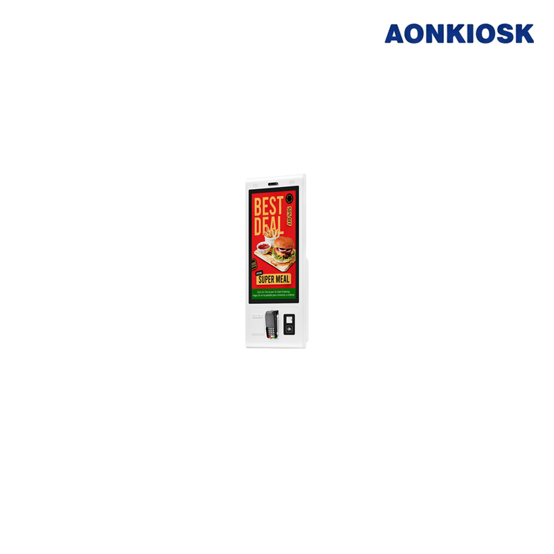
Un kiosque mural est une machine en libre-service compacte dont l'enceinte est soutenue par un système de montage mural plutôt que par un piédestal ou une base au sol.
Selon l'application, le kiosque peut comprendre :
- Écran tactile
- PC industriel ou carte mère Android
- Lecteur de code QR ou de code-barres
- Lecteur NFC
- Terminal de paiement
- Imprimante de reçus ou de billets
- Caméra
- Haut-parleur et microphone
- Indicateur d'état
- Modules réseau et d'alimentation
Les kiosques muraux sont couramment utilisés pour :
- Commande en libre-service en restaurant
- L'enregistrement des visiteurs
- Assistance à l'enregistrement hôtelier
- Délivrance de tickets de file d'attente
- Consultation d'informations sur les produits
- Orientation et répertoires
- L'enregistrement dans les établissements de santé
- Libre-service employé
- Paiement de factures
- Contrôle d'accès
Le format d'installation est particulièrement utile lorsque l'espace au sol est limité ou lorsque l'équipement doit rester à l'écart des circuits de nettoyage, des chariots, des bagages et du flux piétonnier.
Pour une comparaison plus large des formats et composants de kiosques, veuillez consulter le Aperçu de la structure matérielle du kiosque.
2. Principales parties de la structure d'un kiosque mural
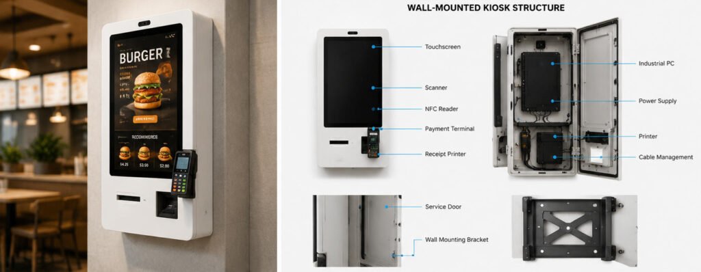
Un kiosque mural fiable se compose normalement de cinq zones structurelles :
- Panneau de commande avant
- Enceinte principale
- Cadre de montage interne
- Structure d'accès pour maintenance
- Ensemble de montage mural
Ces zones doivent fonctionner ensemble comme un seul système mécanique.
2.1 Panneau de commande avant
Le panneau avant est la section du kiosque orientée vers l'utilisateur. Il supporte l'écran tactile et fournit des ouvertures ou des positions de montage pour les périphériques utilisés par l'utilisateur.
Un panneau avant typique peut contenir :
- Ouverture pour écran tactile
- Support pour terminal de paiement
- Fenêtre de scanner
- Zone de lecture NFC
- Fente de sortie d'imprimante
- Ouverture pour caméra
- Perforations pour haut-parleur
- Ouverture pour microphone
- Voyants LED d'état
La position de chaque dispositif doit suivre le flux de travail logiciel. Les dispositifs fréquemment utilisés doivent être visibles et accessibles sans obliger les utilisateurs à s'étirer, à se pencher excessivement ou à se déplacer entre différents côtés du kiosque.
Le panneau avant doit également rester rigide. Une flexibilité excessive peut entraîner le mouvement de la lunette de l'écran tactile, le désalignement des fenêtres de scanner et le desserrage des supports de terminal de paiement lors d'une utilisation répétée.
Selon la conception industrielle, le panneau peut être fabriqué en acier laminé à froid, en acier inoxydable, en aluminium, en verre trempé ou en une combinaison de matériaux. Des conseils supplémentaires sont disponibles dans le Guide de sélection des matériaux d'enceinte de kiosque : métal vs acier.
2.2 Enceinte principale
L'enceinte protège l'ordinateur, l'alimentation électrique, les contrôleurs, les câbles et autres composants internes.
Sa profondeur dépend du matériel installé. Un kiosque d'information de base contenant uniquement un écran et un ordinateur intégré peut utiliser une enceinte relativement fine. Un kiosque de transaction avec imprimante, terminal de paiement, scanner et adaptateurs d'alimentation nécessite un volume interne plus important.
L'enceinte doit fournir :
- Une rigidité structurelle suffisante
- Entrée de câbles protégée
- Ouvertures de ventilation
- Accès de service verrouillable
- Points de mise à la terre internes
- Positions de montage périphériques
- Espace pour le rayon de courbure des câbles
- Dégagement pour le retrait des composants
- Protection contre tout accès non autorisé
Réduire la profondeur de l'enceinte peut améliorer l'apparence, mais rendre l'armoire trop peu profonde crée des problèmes pratiques. Les câbles peuvent exercer une pression contre le panneau arrière, le papier d'imprimante peut être difficile à remplacer, les connecteurs peuvent être endommagés et la chaleur peut s'accumuler derrière l'écran.
La profondeur de l'armoire doit donc être déterminée en fonction de la configuration matérielle finale plutôt que de la seule apparence.
2.3 Cadre de montage interne
Le cadre interne supporte l'écran tactile, l'ordinateur, l'imprimante, les modules d'alimentation et les supports périphériques.
Ce cadre peut être intégré à l'enceinte ou fabriqué comme un ensemble distinct soudé ou boulonné. Il transfère les charges des composants internes à la structure de montage arrière.
Les considérations importantes pour la conception du cadre incluent :
- Poids de l'écran et centre de gravité
- Vibrations de l'imprimante
- Force d'actionnement du terminal de paiement
- Charge de la porte et des charnières
- Trajets de remplacement des composants
- Accessibilité des fixations
- Le cheminement des câbles
- Tolérances de fabrication
Les appareils lourds doivent être fixés à des supports structurels plutôt que directement à un panneau décoratif mince. Une imprimante de reçus, par exemple, peut générer des mouvements à chaque coupe de papier. Sans support rigide, ce mouvement peut progressivement desserrer les vis ou décaler l'alignement de sortie de l'imprimante.
Le cadre interne doit également séparer les zones de service lorsque cela est possible. Les composants d'alimentation, le matériel informatique et les périphériques fréquemment entretenus ne doivent pas toujours occuper le même compartiment.
2.4 Porte de service ou ensemble frontal articulé
Les techniciens ont besoin d'accéder au matériel interne pour :
- Remplacement du papier de l'imprimante
- Retrait des bourrages
- Remplacement de l'ordinateur
- Inspection des câbles
- Maintenance de l'alimentation électrique
- Réglage du scanner
- Nettoyage
- Maintenance logicielle
- Mises à niveau des périphériques
Les structures d'accès courantes incluent :
- Panneau frontal articulé
- Porte latérale articulée
- Panneau arrière amovible
- Panneau de service rabattable
- Plateau interne coulissant
- Armoire de service encastrée
Pour la plupart des bornes murales, l'accès arrière est limité car l'enceinte est installée directement contre le mur. La maintenance doit donc être effectuée depuis l'avant, les côtés, le haut ou le bas.
Un panneau frontal articulé est pratique, mais son poids doit être pris en compte. Les charnières, les vérins à gaz, les câbles de soutien, les points de verrouillage et la direction d'ouverture doivent contrôler le panneau en toute sécurité pendant la maintenance.
Les portes de service ne doivent pas s'ouvrir dans les passages fréquentés ni obstruer les équipements à proximité. Les techniciens doivent également pouvoir ouvrir la borne sans retirer toute la machine du mur.
2.5 Ensemble de montage mural
L'ensemble de montage relie l'enceinte de la borne à la structure du bâtiment. Il peut inclure :
- Plaque murale en acier
- Rails de montage à verrouillage mutuel
- Support compatible VESA
- Cadre arrière renforcé
- Fixations de sécurité
- Points de verrouillage anti-soulèvement
- Chevilles à expansion
- Ancrages chimiques
- Boulons traversants
- Câble de sécurité secondaire
La méthode de montage sélectionnée doit être adaptée au matériau du mur, au poids du kiosque, aux forces d'utilisation et aux exigences d'installation locales.
Un support mural ne doit pas être dimensionné uniquement pour le poids statique du kiosque. Il doit également résister aux forces générées lorsque les utilisateurs appuient sur l'écran tactile, utilisent un terminal de paiement, tirent sur le papier imprimé ou s'appuient accidentellement sur l'enceinte.
3. Structure du mur et exigences de charge
Avant d'installer un kiosque libre-service mural, l'installateur doit identifier ce qui se trouve derrière la surface finie du mur.
Les constructions murales possibles comprennent :
- Béton armé
- Brique pleine
- Brique creuse
- Bloc de béton
- Ossature en acier
- Ossature en bois
- Plaque de plâtre
- Panneaux muraux décoratifs
- Cloisons en verre
Un mur fini peut sembler solide tout en offrant un faible support structurel. Les plaques de plâtre, les panneaux décoratifs minces et les cloisons légères ne peuvent généralement pas supporter un kiosque commercial sans renforcement.
Un renforcement approprié peut nécessiter :
- La fixation dans le béton ou la maçonnerie
- La fixation sur des montants structurels
- L'installation d'une plaque d'appui en acier
- L'ajout d'un renfort en contreplaqué derrière le mur
- La construction d'un cadre de support en acier indépendant
- L'utilisation de boulons traversants et de plaques d'appui
L'installateur doit vérifier :
- Le poids total du kiosque
- Le poids de tous les périphériques installés
- La capacité de charge du support
- Le type et la taille des ancrages
- Le matériau du mur
- L'espacement des ancrages
- Les distances aux bords
- Le facteur de sécurité requis
- La force d'utilisation appliquée par l'utilisateur
- Les exigences locales en matière de construction et de sécurité
La configuration finale du kiosque doit être évaluée. Une enceinte d'essai équipée uniquement d'un écran tactile peut peser considérablement moins que la version de production après l'ajout d'une imprimante, d'un dispositif de paiement, d'un ordinateur, d'une alimentation électrique et de supports internes en acier.
4. Hauteur de l'écran, angle de vision et accessibilité
La hauteur de montage est l'une des dimensions les plus importantes d'un kiosque mural, car elle devient difficile à modifier une fois que les trous dans le mur, les prises électriques et les passages de câbles ont été réalisés.
La conception doit prendre en compte :
- Les utilisateurs debout
- Les utilisateurs assis
- Utilisateurs en fauteuil roulant
- Les enfants lorsque cela est pertinent
- La taille de l'écran
- L'orientation portrait ou paysage
- Les positions des cibles tactiles
- La hauteur du terminal de paiement
- La hauteur du scanner
- La position de sortie de l'imprimante
- Les reflets et l'éclairage
- L'espace d'approche de l'utilisateur
Le centre de l'écran ne doit pas automatiquement être considéré comme le point de référence principal. Les utilisateurs interagissent normalement avec des commandes réparties sur l'écran, et les boutons importants peuvent apparaître près du haut ou du bas de l'interface.
Pour cette raison, l'interface logicielle réelle doit être testée à la hauteur d'installation prévue.
L'angle de vision doit également être évalué. Un écran monté verticalement peut créer des reflets sous un éclairage de plafond, tandis qu'une inclinaison excessive vers le bas peut réduire la lisibilité pour les utilisateurs de grande taille. L'angle de l'écran, le traitement du verre de protection, la luminosité et l'éclairage ambiant doivent être évalués conjointement.
AONKIOSK configure couramment des bornes murales avec des écrans tactiles commerciaux adaptés aux applications compactes de commande, d'enregistrement et d'information. L'écran approprié doit être sélectionné en fonction de la distance de vision, de la complexité de l'interface et de la surface murale disponible. Voir Comment choisir la taille d'écran tactile adaptée pour un kiosque en libre-service pour des recommandations supplémentaires.
Les exigences d'accessibilité diffèrent selon les marchés de déploiement et les applications. Les dimensions finales doivent être vérifiées par rapport aux normes et réglementations applicables sur le lieu d'installation.
5. Agencement interne du matériel
Une enceinte murale présente une profondeur interne inférieure à celle de nombreuses bornes au sol, ce qui rend le placement des composants particulièrement important.
5.1 Écran tactile et affichage
L'ensemble écran tactile occupe généralement la majeure partie de la surface avant. Il peut comprendre :
- Panneau LCD
- Capteur tactile capacitif ou infrarouge
- Verre de protection
- Contrôleur d'affichage
- Câble vidéo
- Câble tactile USB
- Supports de montage
La structure de montage doit empêcher toute pression d'être transférée de manière inégale au panneau LCD ou au capteur tactile.
Un dégagement adéquat doit être maintenu autour des connecteurs. Les connecteurs HDMI, DisplayPort, USB et d'alimentation ne doivent pas être pliés brusquement contre l'enceinte arrière.
Pour obtenir de l'aide sur le choix de la technologie tactile, veuillez consulter Types d'écrans tactiles utilisés dans les bornes libre-service.
5.2 Ordinateur industriel ou carte mère
La plateforme informatique est normalement positionnée derrière ou à côté de l'écran.
Les options courantes incluent :
- PC industriel sans ventilateur
- PC embarqué de type boîtier
- Carte mère Windows
- Carte mère Android
- Ordinateur POS
- Ordinateur sur carte unique
L'ordinateur doit rester accessible sans retirer l'écran dans la mesure du possible. Les techniciens peuvent avoir besoin de remplacer le stockage, de reconnecter des câbles, d'accéder aux ports USB, de réinitialiser le système ou d'échanger l'unité informatique complète.
L'emplacement choisi doit garantir une circulation d'air adéquate et ne doit pas placer l'ordinateur directement à côté d'alimentations à haute température sans évaluation thermique.
5.3 Imprimante
Les imprimantes de reçus et de tickets comptent parmi les composants les plus difficiles à intégrer dans une enceinte murale fine.
La structure doit prévoir de l'espace pour :
- Rouleau de papier
- Mouvement de chargement du papier
- Mécanisme de coupe
- Chemin du papier imprimé
- Accès aux connecteurs
- Retrait des bourrages
- Remplacement du rouleau
- Nettoyage des capteurs
La fente de sortie doit être alignée avec le chemin de l'imprimante et empêcher le papier de se recourber à l'intérieur de l'enceinte.
Le personnel de maintenance doit pouvoir remplacer le rouleau de papier sans avoir à soutenir une porte avant lourde ni à déconnecter des composants sans rapport.
Si de grands rouleaux de papier, plusieurs imprimantes, l'impression de documents ou une maintenance fréquente sont requis, une enceinte plus profonde ou une installation partiellement encastrée peut être plus appropriée.
5.4 Scanner, lecteur NFC et terminal de paiement
Les scanners et les dispositifs de paiement doivent être positionnés en fonction de la séquence de transaction.
Un flux de travail typique peut être :
- Sélectionner un service sur l'écran tactile.
- Scanner un code QR ou une carte de membre.
- Confirmer la transaction.
- Payer par carte ou par méthode sans contact.
- Récupérer le reçu imprimé.
Le positionnement des périphériques doit soutenir naturellement cette séquence.
Les fenêtres de scanner nécessitent une distance et un angle corrects par rapport au moteur de numérisation. Les antennes NFC ne doivent pas être installées directement derrière du métal, sauf si la conception du lecteur prévoit une isolation appropriée. Les supports de terminal de paiement doivent résister aux insertions répétées de cartes, à la saisie du code PIN et aux tapements sans contact.
Pour les projets impliquant des transactions de détail, les configurations compatibles peuvent être examinées dans Bornes de vente au détail et de paiement.
6. Alimentation électrique, données et acheminement des câbles
La planification des câbles doit être effectuée avant la finition du mur.
Un kiosque mural peut nécessiter :
- Alimentation secteur
- Ethernet
- Rallonges USB
- Câbles vidéo
- Câbles audio
- Câbles d'antenne
- Alimentation des périphériques
- Câblage d'alarme ou de contrôle d'accès
Les méthodes courantes d'entrée de câbles comprennent :
- Conduit mural dissimulé
- Entrée de câbles par l'arrière
- Entrée de câbles par le bas
- Goulotte de câblage en surface
- Boîtier électrique encastré
- Conduit métallique flexible
L'entrée arrière dissimulée produit normalement l'installation la plus propre, mais la prise murale et la position du conduit doivent être alignées avec précision sur l'ouverture du kiosque.
La zone d'entrée des câbles ne doit pas interférer avec le support mural. Les câbles doivent également disposer d'une longueur de service suffisante pour que le panneau avant ou le plateau interne puisse s'ouvrir en toute sécurité.
À l'intérieur du kiosque, les câbles d'alimentation et les câbles de signaux basse tension doivent être acheminés de manière ordonnée et maintenus à l'aide de colliers, d'attaches, de goulottes ou de supports de décharge de traction. Les câbles ne doivent pas entrer en contact avec les dispositifs de coupe d'imprimante, les charnières de porte, les bords métalliques tranchants, les ventilateurs ou les composants chauds.
Toutes les pièces métalliques exposées doivent être mises à la terre conformément à la conception électrique. Le kiosque doit également offrir une méthode contrôlée de déconnexion de l'alimentation pendant les opérations de maintenance.
7. Ventilation et gestion thermique
Les kiosques muraux disposent souvent d'un volume d'air interne limité et d'un espace réduit derrière l'enceinte.
La chaleur peut être générée par :
- Rétroéclairage LCD
- Ordinateur industriel
- Alimentation électrique
- Terminal de paiement
- Imprimante
- Modules de charge
- Équipements de communication
Les options de gestion thermique comprennent :
- Ouvertures de ventilation passive
- Des ventilateurs de circulation interne
- Entrées d'air filtrées
- Plaques de montage conductrices de chaleur
- Ordinateurs sans ventilateur à faible consommation
- Des ventilateurs à contrôle de température
- La séparation des composants générateurs de chaleur
Les ouvertures de ventilation doivent être positionnées de manière à ce que l'air chaud puisse s'élever et quitter l'enceinte tandis que l'air plus frais entre par le bas. Toutefois, la taille et la position des ouvertures doivent également empêcher les utilisateurs d'atteindre le câblage interne ou d'insérer des objets étrangers.
Un kiosque installé dans une cavité murale encastrée nécessite une attention particulière. La cavité peut piéger la chaleur même lorsque l'enceinte elle-même comporte des ouvertures de ventilation.
Les essais thermiques doivent être effectués avec le matériel équivalent à la production fonctionnant dans des conditions ambiantes attendues. Tester uniquement l'enceinte vide ne confirme pas que le kiosque complet peut fonctionner de manière fiable.
Les installations murales extérieures ou semi-extérieures nécessitent une protection environnementale supplémentaire, une étanchéité, un contrôle de l'exposition au soleil et une planification de la condensation. Ces applications doivent être évaluées à l'aide du Guide des exigences pour kiosques extérieurs.
8. Conception de la sécurité
Étant donné qu'un kiosque mural est souvent installé dans des lieux publics ou semi-publics, les utilisateurs ne doivent pas pouvoir accéder aux composants électroniques internes ni retirer la machine de son support.
Les dispositifs de sécurité peuvent comprendre :
- Fixations de montage dissimulées
- Serrures de support anti-soulèvement
- Portes de service verrouillables
- Vis de sécurité
- Charnières renforcées
- Protection interne des câbles
- Interrupteurs anti-intrusion
- Ports USB protégés
- Accès restreint à l'interrupteur d'alimentation
- Supports de sécurité pour terminaux de paiement
Les serrures doivent être positionnées de manière à ce que le personnel autorisé puisse y accéder sans qu'elles soient visibles pour les utilisateurs.
Le rail de montage doit empêcher le boîtier d'être soulevé ou glissé après l'installation. Une vis de retenue secondaire ou un support interne peut verrouiller le kiosque sur la plaque murale.
Les exigences de sécurité doivent correspondre à l'application. Un terminal de commande en restauration supervisée présente des risques différents d'un kiosque de paiement sans surveillance installé dans une station de transport.
9. Procédure d'installation
Le processus d'installation exact dépend de la conception du mur et du support, mais une procédure type comprend les étapes suivantes.
Étape 1 : Confirmer l'emplacement d'installation
Vérifier :
- Circulation des utilisateurs
- Hauteur de fonctionnement
- Accessibilité
- Portes et équipements à proximité
- Éclairage et reflets
- Espace de maintenance
- Disponibilité de l'alimentation électrique et du réseau
- Exigences relatives aux voies d'évacuation d'urgence
Étape 2 : Inspecter le mur
Identifier le matériau du mur et le support structurel. Ne pas se fier uniquement à la surface visible.
Étape 3 : Confirmer le poids final de l'équipement
Inclure le boîtier, l'écran, l'ordinateur, l'imprimante, le rouleau de papier, le dispositif de paiement, les scanners, les modules d'alimentation, les supports et les câbles.
Étape 4 : Marquer la position du support
Utiliser le plan d'installation approuvé ou le gabarit de montage. Vérifier l'alignement horizontal et la hauteur par rapport au sol fini.
Étape 5 : Installer les ancrages appropriés
Utiliser des ancrages spécifiés pour la structure réelle du mur et la charge de conception. Les ancrages endommagés, desserrés ou mal positionnés ne doivent pas être réutilisés.
Étape 6 : Installer les connexions électriques et de données
Acheminer les câbles par le point d'entrée prévu tout en maintenant la décharge de traction et la longueur de service.
Étape 7 : Fixer la plaque murale
Serrer les fixations uniformément et vérifier que la plaque est plane et sécurisée.
Étape 8 : Monter le kiosque
Cette étape peut nécessiter deux installateurs ou plus, selon la taille et le poids de l'équipement. Le levage doit suivre les instructions de manipulation du fabricant.
Étape 9 : Sécuriser le verrou anti-soulèvement
Installer les fixations de retenue, les vis de verrouillage ou le câble de sécurité empêchant le retrait du kiosque du support.
Étape 10 : Tester le système complet
Vérifier :
- Stabilité structurelle
- Fonctionnement de l'écran tactile
- Communication réseau
- Fonctionnement de l'imprimante
- Alignement du scanner
- Accès au terminal de paiement
- Fonctionnement des portes et serrures
- La ventilation
- Dégagement des câbles
- Flux de travail logiciel
10. Exigences de maintenance
Une maintenance régulière permet de prévenir les pannes causées par la poussière, les fixations desserrées, les câbles endommagés et les chemins d'impression obstrués.
Les contrôles recommandés comprennent :
- Nettoyer l'écran tactile et le verre de protection.
- Inspecter les fenêtres du scanner et de la caméra.
- Retirer la poussière de papier de l'imprimante.
- Vérifier l'état du rouleau de papier.
- Inspecter les charnières et les ressorts à gaz.
- Confirmer que les serrures fonctionnent correctement.
- Vérifier les fixations de montage.
- Inspecter la décharge de traction des câbles.
- Retirer la poussière des ouvertures de ventilation.
- Confirmer que les ventilateurs fonctionnent normalement.
- Vérifier toute chaleur ou tout bruit inhabituel.
- Tester les dispositifs de paiement et de numérisation.
- Examinez les journaux d'erreurs système.
L'intervalle de maintenance doit refléter l'utilisation. Un restaurant à fort volume ou un kiosque de transport peut nécessiter un entretien plus fréquent de l'imprimante et de l'écran tactile qu'un terminal d'information à faible trafic.
11. Problèmes courants et dépannage
Le kiosque bouge lorsque l'écran est pressé
Causes possibles :
- Ancrages muraux desserrés
- Structure murale flexible
- Renfort de support insuffisant
- Plaque murale desserrée
- Jeu excessif du support
- Panneau arrière déformé
Cessez d'utiliser le kiosque si le système de montage semble dangereux. Inspectez le mur, les ancrages, le support et l'enceinte avant de remettre la machine en service.
Le panneau avant ne se ferme pas correctement
Vérifiez :
- Câbles coincés près du bord
- Rouleau de papier installé incorrectement
- Support interne desserré
- Serrure désalignée
- Charnière pliée
- Périphérique dépassant de sa zone de montage
Ne forcez pas la fermeture du panneau, car cela pourrait endommager les câbles, les connecteurs ou l'écran.
L'imprimante se bloque fréquemment
Les causes possibles incluent :
- Type de papier incorrect
- Fente de sortie désalignée
- Chemin du papier restreint
- Couteau de coupe sale
- Rouleau de papier installé dans le mauvais sens
- Espace insuffisant autour de l'imprimante
Testez l'imprimante avec le papier de production réel et vérifiez que le chemin de sortie du boîtier correspond aux exigences du fabricant de l'imprimante.
Le kiosque surchauffe
Inspecter :
- Évents d'aération obstrués
- Ventilateur en panne
- La lumière ambiante vive
- Température ambiante excessive
- Ventilation encastrée dans le mur inadéquate
- Composants de remplacement à haute puissance
- Placement incorrect de l'alimentation électrique
Mesurez les températures internes pendant le fonctionnement normal plutôt que de vous fier uniquement à la température externe du boîtier.
L'opération tactile est instable
Vérifier :
- Mise à la terre
- Maintien du câble USB
- Interférences électromagnétiques
- Humidité sur l'écran
- Verre de protection endommagé
- Connexion du contrôleur tactile
- Pression exercée par le cadre de montage
Si le problème est apparu après l'installation, vérifiez que le cadre de l'écran tactile n'a pas été déformé lorsque l'enceinte a été serrée contre un mur inégal.
Les connexions réseau se déconnectent par intermittence
Inspecter :
- Maintien du connecteur Ethernet
- Rayon de courbure des câbles
- Stabilité de l'alimentation
- Statut du routeur ou du commutateur
- Position de l'antenne
- Interférence de l'enceinte métallique
- Dommages aux câbles près de la charnière
Les antennes sans fil peuvent nécessiter d'être positionnées à l'extérieur des sections fortement blindées de l'enceinte métallique.
12. Montage mural, encastré ou sur socle au sol ?
Un kiosque mural est adapté lorsque :
- L’espace au sol est limité.
- Le mur peut supporter l’équipement.
- Les périphériques requis s’intègrent dans un boîtier compact.
- Une maintenance avant ou latérale est possible.
- Les utilisateurs s’approchent du kiosque depuis une direction prévisible.
Un kiosque encastré peut être plus adapté lorsque :
- Une apparence architecturale affleurante est requise.
- La cavité murale offre une profondeur suffisante.
- Un accès de service arrière est disponible.
- La ventilation peut être intégrée dans le mur.
Un kiosque sur socle au sol peut être plus adapté lorsque :
- Le mur ne peut pas supporter la charge.
- Des imprimantes volumineuses ou des modules de caisse sont requis.
- Le kiosque peut être déplacé.
- Un espace d’extension interne plus important est nécessaire.
- L’installation ne peut pas modifier le mur du bâtiment.
La décision doit être fondée sur le flux de travail complet, la liste des composants, les conditions du bâtiment, les exigences d’accessibilité et le processus de maintenance — et non sur le seul aspect esthétique.
13. Liste de spécifications pour kiosque mural
Avant de demander un devis ou d’approuver une conception, définissez :
- Application et flux de travail utilisateur
- Environnement intérieur, semi-extérieur ou extérieur
- La taille et l'orientation de l'écran
- La technologie de l’écran tactile
- Le système d’exploitation
- Les performances informatiques
- Le modèle d’imprimante et le format de papier
- Le modèle de scanner
- Les exigences NFC ou RFID
- Modèle du terminal de paiement
- Les exigences caméra et audio
- Le matériau et la finition du boîtier
- Le poids total du produit
- La construction du mur
- La hauteur de montage
- Les exigences de support et d’ancrage
- Position du câble d’entrée
- La méthode de ventilation
- La direction d’accès de maintenance
- Les exigences de verrouillage et de sécurité
- Exigences d'accessibilité
- Exigences de certification
- La méthode d’emballage et d’installation
La fourniture de modèles de périphériques exacts est importante, car des dispositifs aux fonctions similaires peuvent avoir des dimensions, des connecteurs, des besoins de ventilation et des chemins de maintenance différents.
14. Ingénierie des kiosques muraux AONKIOSK
AONKIOSK développe des équipements de kiosque libre-service configurables et personnalisés pour les applications de commande, paiement, enregistrement, billetterie, information, commerce de détail, hôtellerie et services publics.
La personnalisation des kiosques muraux peut inclure :
- Les dimensions du boîtier
- Affichage portrait ou paysage
- Taille de l’écran tactile
- Conception du support mural
- Disposition des composants internes
- L'intégration d'imprimantes
- Modules scanner et NFC
- Supports pour terminaux de paiement
- Modules caméra et audio
- Positions d’entrée des câbles
- Conception de la ventilation
- Verrouillage et accès de service
- Couleur de surface et image de marque
Une conception prête pour la production doit être évaluée à l’aide de l’écran, de l’ordinateur, de l’imprimante, du scanner, du dispositif de paiement et de la méthode d’installation réels. Un prototype permet à l’équipe de projet de vérifier la hauteur de fonctionnement, l’ergonomie de l’interface, la charge murale, le cheminement des câbles, les performances thermiques, l’accès de maintenance et la compatibilité logiciel-matériel avant la production en série.
La gamme de kiosques Fabrication de bornes libre-service OEM et ODM Le service accompagne les projets depuis l'évaluation des exigences et la conception mécanique jusqu'au développement de prototypes, aux tests, à la production, à l'inspection qualité et à la livraison mondiale.
Conclusion
Une borne murale fiable dépend de bien plus qu'un boîtier compact. La structure du mur, le support de montage, le châssis interne, la disposition des composants, l'entrée des câbles, la ventilation, l'accessibilité, la sécurité et la méthode de maintenance doivent être conçus comme un système complet et intégré.
Les décisions les plus importantes du projet doivent être prises avant la finition du mur et avant que le boîtier de la borne n'entre en production. Confirmez la construction réelle du mur, le poids total de l'équipement, les modèles finaux des périphériques, la hauteur de montage, les connexions électriques et le processus de maintenance.
Lorsque ces facteurs sont validés par une revue d'ingénierie et des tests sur prototypes, une borne libre-service murale peut constituer une alternative compacte, sécurisée, maintenable et économe en espace par rapport à un terminal au sol.